

Growing Appeal of PCD: Turning Performance
How might PCD tool technology affect your business? Could it be the key to faster cycle times, longer tool life and better surface quality? To answer these questions, we must first review what you need to know about using PCD tools.
Review the print ads from this magazine to continue
This quick advertiser review unlocks the rest of the article and keeps the full-screen reader focused on the ads instead of the page chrome.
Advertisers included in this article experience
Print placements connected to this article
Mfgaxis
Where buyers and builders connect
Where buyers and builders connect Visit mfgaxis.com to learn more.
Visit Mfgaxis View this placement in the issue recordPrint ads from this magazine
Where buyers and builders connect Visit mfgaxis.com to learn more.
Continue reading
March 2026
How might PCD tool technology affect your business? Could it be the key to faster cycle times, longer tool life and better surface quality? To answer these questions, we must first review what you need to know about using PCD tools.
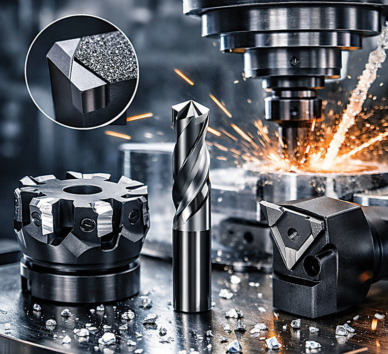
Some PCD background
PCD stands for “polycrystalline diamond,” and the name itself reveals a lot about what the material actually is. Structurally, sintered tungsten carbide and PCD are quite similar. Both are composites — materials made from two parts that retain some beneficial properties of each. In the case of carbide, millions of very hard grains of tungsten carbide are held together in a metallic binder, almost always cobalt. In simple terms, carbide owes its hardness to the tungsten carbide grains, and its toughness to the metallic binder.
PCD is essentially the same, except that grains of tungsten carbide are replaced with millions of tiny diamonds. Diamonds being much harder than tungsten carbide, the result is a material with a hardness that far exceeds any other cutting tool material.
But simply creating a harder cutting tool material doesn’t mean that it should be used in every possible application. Knowing when to use PCD cutting tools requires an understanding of how PCD can be tuned for optimal performance in different applications.
First, manufacturers can control the average size of their diamond grains. Smaller grains will limit plastic deformation and promote more intimate linking between individual grains (each grain will be touching more neighbors), ultimately making the material harder. Like carbide, PCD made from smaller grains will also be able to hold sharper cutting edges, so these materials are often used for finishing applications. PCD grades made from more coarse grains offer better wear resistance in materials like GFRP, CFRP, and high-silicon aluminum alloys.
Second, manufacturers can control the amount of metallic binder used in their PCD. Increasing the binder content will make PCD softer but tougher — more suitable for interrupted cutting — but this will also reduce PCD’s ability to hold a sharp cutting edge, which is essential for applications requiring fine finishes. Depending on how the PCD is manufactured, the binder might be mixed in with diamond grains as cobalt powder before sintering, or manufacturers might simply rely on the movement of liquid cobalt from nearby tungsten carbide when sintering temperatures reach the melting temperature of the cobalt.
Third, and less well-known, manufacturers can also tune the properties of PCD by controlling the shape and size distribution of the diamond grains and the quality of the binder. Monitoring these characteristics is one area where high-quality manufacturers might distinguish themselves from low-cost competitors. For example, more rounded diamond grains or more faceted diamond grains will interact with one another and with the binder differently. In some cases grains are chosen to provide a more intimate bonding between neighboring grains during sintering, which improves hardness; in others, a more intimate bond with the binder is desirable, improving toughness. During sintering, the cobalt binder also acts as a catalyst to promote recrystallization, which may or may not be desirable depending on the needs of the application. On the other hand, more sharply faceted grains will not compact as closely and will reduce the bond between neighboring grains. The average size distribution also plays a role because occasional larger grains — if plucked out during the final shaping process — will leave a larger “hole” that can negatively affect the quality of the cutting edge and surface finish.
Diamond grains and binder content aside, PCD is always manufactured by sintering at a high temperature and an extremely high pressure. In some cases, PCD is formed on top of a tungsten carbide wafer or disc, after which larger wafers are “diced” into shapes using a laser or wire EDM (electrical discharge machine).
Eventually these shapes are brazed onto the body of a cutting tool and sharpened. In other cases, PCD is formed inside a “slit” in a tungsten carbide cylinder. These cylinders can be brazed to drill bodies and carefully shaped into drills where the PCD forms only the cutting edges.
Given the fact that PCD is so hard, shaping PCD into an accurate cutting tool has always proved challenging to manufacturers, and many view this step as something that makes their tools superior to others. Three methods are used.
Many PCD cutting tools are physically ground using diamond grinding wheels. While this method can create cutting edges where individual diamond grains actually become sharpened, it requires physical contact that can break delicate tools and can occasionally “pluck” diamond grains out of the binder. Also, the diamond grinding wheels wear nearly as fast as the PCD.
Other PCD tools are shaped using electrical discharge machining (EDMing). Being non-contact, this process can accurately and safely shape delicate tools; but individual diamond grains are not electrically conductive, which means they simply fall out as the conductive binder around them is removed. Ultimately this means that cutting edges don’t contain sharpened diamond grains.
Lastly, PCD tools can be shaped using laser ablation, which is becoming more common. Although ideally suitable for shaping PCD, some manufacturers argue that the heat from laser ablation will cause nearby diamonds to decompose into graphite, dramatically reducing the usefulness of the cutting edge. While this is a legitimate concern, there is strong evidence that modern femtosecond lasers eliminate this problem by pulsing the laser so quickly that heat doesn’t have time to travel into the nearby diamond (one femtosecond is to one second as one second is to 30 million years). Using femtosecond lasers, ablation is recognized as the most sophisticated way to shape PCD cutting edges, and can be used to make micro-tooling where the entire tool body is solid PCD and cutting edges actually contain sharpened diamond grains; but currently the equipment is very expensive.
When not to use PCD
In practical terms, knowing what PCD is and how it is manufactured will help you understand when to use PCD tools. But it’s often more helpful to begin by talking about when not to use PCD, and that requires a discussion about PCD’s limitations.
First, the toughness of PCD is relatively low compared to carbide, thus it is more prone to brittle failure. This means that vibration should be avoided, and highly rigid toolholding and workholding are essential. Toolholders should be clean, stout and as short as possible. Drawbar force should be adequate, the spindle taper should be in good condition, and pull studs (when used) must not be overtorqued or worn badly. Ultimately, this means that PCD cutting tools should not be used without careful consideration of the setup and machine involved. In some cases, the machine or workpiece might not be rigid enough to use PCD tools, despite an operator’s best efforts.
Second, PCD is uniquely sensitive to temperature for several reasons. Alone, diamond will decompose into graphite around 1,700° C, but the diamond in PCD begins to decompose around 700° C because cobalt acts as a catalyst to promote graphitization. Cobalt readily dissolves into diamond, which makes it an ideal binder material that “sticks” to the diamond grains quite well; but this affinity also has negative effects. Cobalt atoms dissolved inside the diamond lattice will weaken atomic carbon bonds and reduce the energy required for decomposition. Graphitization aside, cobalt also has a much higher coefficient of thermal expansion than diamond. If the tool becomes too hot, the cobalt binder can expand so much that individual diamond grains become dislodged from the cutting edge. Furthermore, PCD tools often contain one or more brazed joints, and even the best brazed joints will begin to soften around 600° C to 950° C. All of these concerns are the main reasons PCD is not yet used to cut materials like titanium and nickel, where cutting temperatures are usually high.
Third, if they come into contact with iron, the carbon atoms in diamond grains will readily diffuse into the iron and form iron carbide (Fe3C), especially at elevated temperatures. This will lead to gradual erosion of the diamond as it loses atoms to the iron around it, and this ultimately means that PCD is not effective for cutting ferrous materials in most situations.
Knowing these limitations also helps us see several applications where PCD cutting tools truly shine.
When to use PCD
Assuming they are used correctly, PCD cutting tools offer three primary advantages.
The most significant advantage is usually a reduction in cycle time. PCD can hold sharper edges, has a much smoother rake face that reduces built-up-edge (BUE), and has a higher thermal conductivity than carbide. Because of this, typical surface speeds for PCD in aluminum are three to five times higher than carbide. Assuming you have a spindle that allows you to take advantage of these extreme surface speeds, cycle time could be reduced by that same factor, directly affecting your profitability. This potential reduction in cycle time is what might motivate an automotive manufacturer to spend over $10,000 on a single PCD face mill. The savings from a reduction in cycle very soon outweigh the cost of the tooling. But if you’re already maxing out your spindle speed running carbide, then switching to PCD won’t help you in this area.
The second most common reason to use PCD cutting tools is improved surface finish. PCD’s hardness and ability to hold a sharp cutting edge make it capable of creating low-roughness surfaces. In situations where roughness must be controlled carefully, either for aesthetic reasons or for functional sealing surfaces, this can make the difference between success and scrap. But vibration must be avoided, and the entire machine and toolholder assembly needs to be considered as a system.
Lastly, PCD cutting tools are used because they offer increased tool life (and thus better process reliability) in abrasive materials. Cast aluminum parts, with their elevated silicon content, are known for wearing carbide tools. In many cases, switching to PCD can increase tool life tenfold (or more). As automotive manufacturers are fighting to make their EVs lighter by using more cast aluminum, their suppliers are turning to custom PCD cutting tools to increase tool life. This helps them machine these components profitably, not only by reducing cycle time, but also by giving them more confidence in the process — something necessary for automation. Beyond aluminum, other abrasive non-metallic materials are often machined using PCD. Aerospace manufacturers are turning to PCD tools to trim carbon-fiber panels and drill holes in multi-material laminations containing carbon fiber reinforced polymers, and circuit board manufacturers are using PCD tools to drill and trim fiberglass-re-inforced materials. The commercial woodworking industry is also dominated by PCD cutting tools. The benefit here goes beyond any direct reduction in tooling cost a shop achieves. In many cases manufacturers are seeking to improve process-reliability so that they can trust tools and safely run processes with less oversight and less variation from part-to-part.
Although PCD tools do have more unique limitations than carbide tools, there are companies working to overcome these limitations. Companies like Sumitomo offer “binderless” PCD grades that can be used to machine materials like tungsten carbide and ceramics. Some research also suggests that binderless grades are the future of machining titanium and nickel alloys. Innolite GmbH successfully uses monocrystalline diamond to machine ferrous materials by oscillating the tool at high frequency, where intermittent contact prevents the diffusion of carbon into the iron. Companies like NS Tool offer spherical PCD tools (without cutting edges) for burnishing steel molds and increasing the diameter of holes. Moving slowly to keep temperatures low, these tools can achieve finishes unthinkable with other tools, even in ferrous metals. Other companies are investigating specialized coatings that promise to protect the PCD substrate from elevated temperatures.
Will PCD change the cutting tool industry in the same way that carbide did, and could PCD tooling offer your shop the next leap in productivity? The answers are not simple, but there are cases in which PCD tools can make a big difference. In the future, chances are those cases will become more common.

about the author
Andrew Schiller is an engineering instructor at Utah Tech University in St. George, Utah, where he teaches product design and manufacturing. He spent nine years working in engineering for Caterpillar and GE Appliances before joining Utah Tech. Email him at Andrew.Schiller@utahtech.edu.
Related




Subscribers can use MFGAxis notes, saves and discussion tools with their innoNET account.


