Deburring and chamfering: Design & Engineering
Manual deburring and chamfering of machined parts can be arduous, but an automated process is faster and more repeatable.
By James Engineering
Deburring is one of the drawbacks of CNC machining. Do you manually handle it with shop floor personnel using a knife, or do you program a machining center to do it?
If it’s the former, your machine operators or other employees must devote time to that instead of performing different — maybe more valuable — tasks. Plus, results vary from person to person.
If it’s the latter, the machine is tied up performing cleanup work when the machine could be on to the next complex part. Perhaps worse, swarf or abrasives from deburring operations can work their way down to the machine’s linear guides and ballscrews, which could reduce its positioning accuracy and eventually bring that critical piece of equipment down for repair.
Vibratory tumbling is another option. However, this might require masking of vital part features, and for shops with only one such machine, frequent setups may be in store because different media will be required for different jobs.
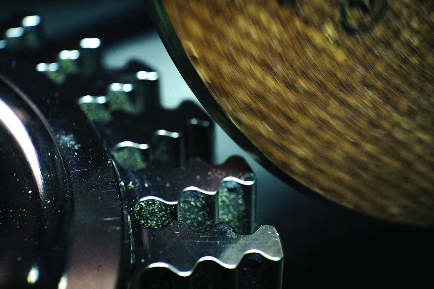
A close-up view is given of a grinding wheel deburring a fir tree rotor intended for a jet engine. Image courtesy of James Engineering
James Engineering in Broomfield, Colorado, builds an automated alternative with its 11-axis Max System CNC deburring and chamfering machine that includes proprietary compliant technology to speed and simplify programming, setup and operation. Compliant technology enables deburring and chamfering tools to maintain a constant force on a part as they follow its features.
Gearing Up
James Richards started the company in the early 1980s. At the time, he developed precision deburring and chamfering techniques to finish gears used in Formula One race cars. He went on to create hundreds of custom gear deburring and chamfering machines for advanced applications in automotive, aerospace and myriad other industries. His most recent development, the Max System, allows the process to be applied not only to gears and shaft components but to prismatic ones.
This machine consists of two five-axis heads and a c-axis rotary table. Servos position the heads via an x/y/z overhead gantry using hardened chrome, ground shafts and carriers with multiple pre-loaded bearings. Movements as fast as 1,500 ipm are possible. Plus, the overhead design means that swarf and abrasive material won’t work their way down into the carrier or onto the gantry shafts. In addition, the machine features nozzles that deliver water-based coolant with rust
inhibitor at 200 gpm not only to keep parts and tools cool during operations but to wash parts and the machine work zone. The two heads can concurrently perform finishing operations using various brushes and abrasive tools to minimize overall cycle times.
Richards also developed a compact 4,000 psi hydraulically driven motor for the heads, providing up to 25,000 rpm using only one moving part and no vanes. Twelve types of tools are available. These install into heads using one bolt.
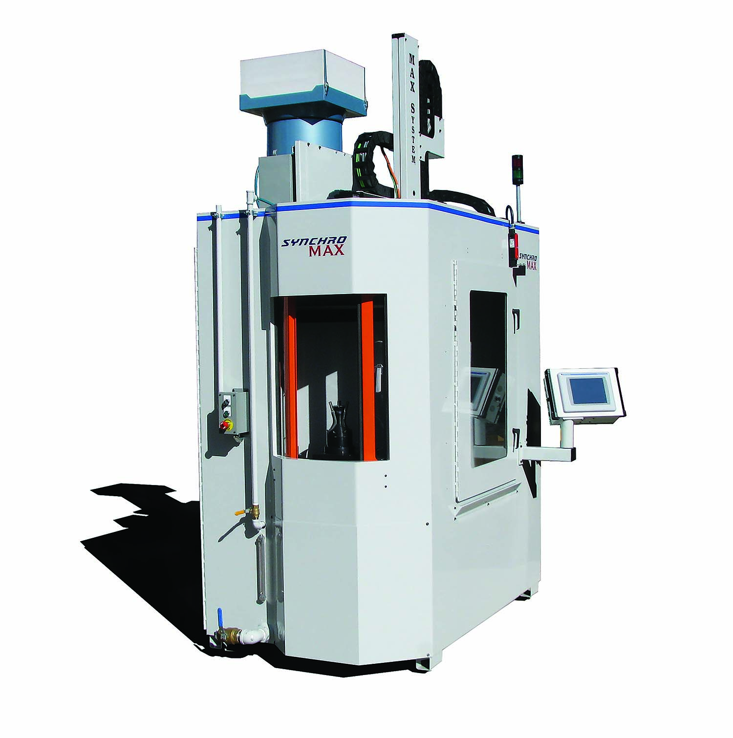
The SynchroMax SM4 is ideal for higher-production facilities that need to maximize operators. Image courtesy of James Engineering
The heart of this process is the compliant technology, which he likens to the front suspension of a car. Using pneumatics and a damping agent enables a tool to maintain a constant force on a part as the tool follows the contour of the features ahead of it to be finished. This means that no change to a programmed toolpath is required to adjust for a perishable tool, such as a brush that might start at 1.25″ in diameter and be reduced to 0.75″ over its life. (Another compliant technology analogy is the way that a record player needle follows the grooves in an album.) This also simplifies programming and setup.
Review the print ads from this magazine to continue
This quick advertiser review unlocks the rest of the article and keeps the full-screen reader focused on the ads instead of the page chrome.
Continue reading
June 2023
QR codes and videos from this issue
Print QR codes, video callouts, and in-magazine links for this article now point to the CTE video hub in the HTML version.