A little math equals a lot of safety
Machine economically and safely by estimating the forces involved with aggressive metal removal.
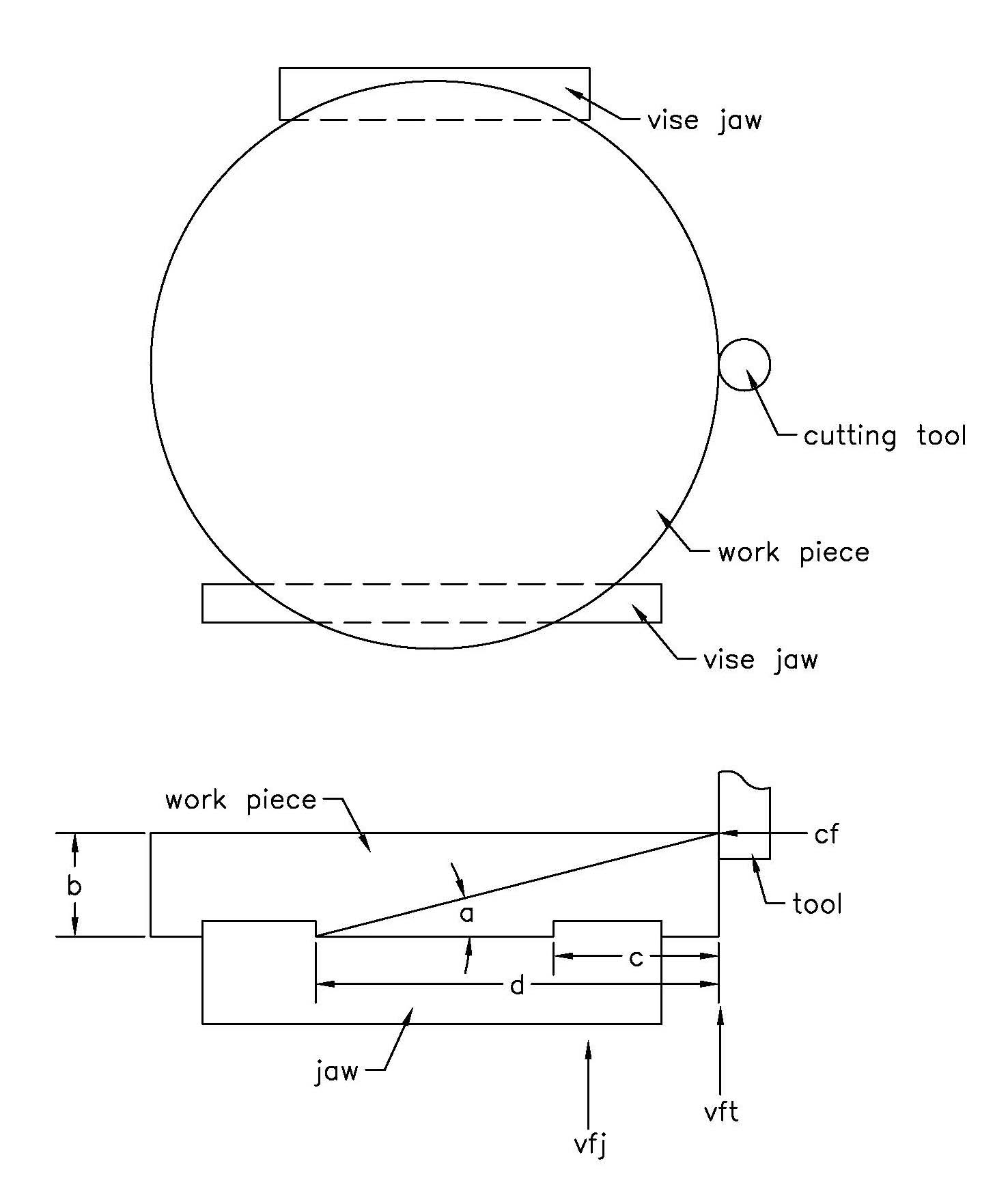
In my previous column, I went through how to hold an 11″-dia.-by-2″-thick workpiece on a 6″ milling vise. This column will showcase a little math to estimate forces involved with aggressive metal removal. In this way, it is possible to machine economically and safely. The drawing shows the problem.
This 190-cubic-inch piece of stock is going to turn into a 75-cubic-inch finished part. To begin, 40 cubic inches will be removed from the outside diameter above where the part is clamped in the vise. When roughing, I use corncob endmills that have little bumps on the flutes, but the math that I use is adaptable to whatever tools you like.
In the drawing, when the tool moves laterally into the workpiece or moves radially around the workpiece center, it will make tangential cutting force CF, which will resolve itself into a horizontal and a vertical component determined by angle a. At the tool, that produces vertical force VFT, which is CF tan a, or CF times a/d. The important thing to consider is the vertical force at the vise jaw clamping surface VFJ, which is higher than VFT because of mechanics. VFJ equals VFT times d/d-c.
If VFJ gets close to the vertical holding power of the clamping surface, then there will be trouble. In the article about the vise jaws for this part, it was determined that 3,600 lbs. of vertical force could be resisted by the steel back jaw holding this aluminum part. There are two clamping surfaces on this jaw, so that’s 1,800 lbs. per surface.
Cutting speed and chip thickness are best determined the normal way to maximize tool economy, but the depth and width of cut can be adjusted for good, safe metal removal.
This 190-cubic-inch piece of stock is going to turn into a 75-cubic-inch finished part. Image courtesy of B. Taylor
Determining CF is the key to the puzzle. The tensile strength of the workpiece with the size and number of the chips will give a useful number.
CF = TGNHJR/W
Where
T = tensile strength of the
workpiece
G = width of the chips (for some tools, this is the depth of cut)
H = chip thickness
J = (number of flutes)/2
Review the print ads from this magazine to continue
This quick advertiser review unlocks the rest of the article and keeps the full-screen reader focused on the ads instead of the page chrome.


MFGAxis Discussion