The challenge of threading: Safety, Standards & Compliance
When done right, threading is very satisfying.
Threading is the most challenging of the basic machining operations. Countless combinations of thread forms and thread classes can complicate tool selection and programming.
Understanding thread requirements is the first step toward success. When properly specified, the thread callout not only contains the basic thread size like 10-24 or ¼-20 but specifies the thread class, which controls the fit between mating components, and the thread form, also known as the thread series, which designates thread geometry.
The class of fit is denoted by a 1, 2 or 3 and followed by an A or a B indicating external thread (A) or internal thread (B). For example, ¾-10 2A is ¾” major diameter with 10 threads per inch and a class 2 fit or tolerance band.
Taps, dies and other threading tools are made to produce threads to a specific thread class, so it is necessary to know which class is required to get the right tools. I learned this the hard way when I ran my family shop. We won a big order to machine aluminum extrusions, and the parts called for three holes tapped 10-24 2B. Instead of purchasing a good “go/no go” thread gauge, we checked the thread quality using a 10-24 screw and the policy of “If the screw goes in, it must be good.” We proudly shipped 1,000 parts to our customer, which promptly rejected all the parts because the pitch diameter was too large. There is no way to rework a tapped hole that is too large, so we had to scrap the parts. It was an expensive lesson in proper thread fit.
Drawings clearly show geometric requirements for a workpiece, such as steps, diameters, corner radii, chamfers and other similar features. However, threading is different as drawings rarely show geometric requirements for threads. Thread geometry is governed by the thread form or thread series like UNC, UNF, BSW, BSF and NPT. The thread series dictates the size, shape, angles and various ratios that define the geometry of threads. A common designation would be ¼-20 UNC 2B, which indicates the unified thread series for coarse threads.
Once the thread series is known, a machinist or programmer can find the various ratios, dimensions and angles in a reference like Machinery’s Handbook. This information is critical for determining pitch diameter, overall thread depth and radii explicit to the thread form. These details are needed to begin the thread machining or programming process.
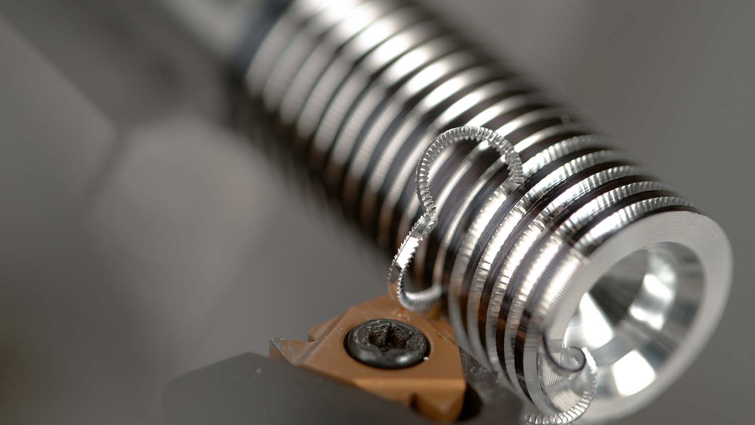
Understanding thread requirements is the first step toward success. Cutting Tool Engineering image
In some cases, thread forms are particular to an industry. Oil and gas, for instance, conforms to specifications given by the American Petroleum Institute, which dictates thread forms designed for strength and safety in the industry. In these situations, it may be necessary to consult a specific standard to obtain accurate thread form data.
The advent of ISO standards and globalization has greatly reduced the variation in thread forms used in modern manufacturing, but older equipment can have obscure thread forms, so a machine shop can’t always assume that a thread is a common form. The British Standard Whitworth thread is an
example of an early thread form used by British manufacturers that is no longer in use. However, old British machines and tools, especially those in niche industries, are still in use, and repairing them or replicating parts often requires special threading tools.
Once the thread form is known, it is necessary to select the threading tool. External and internal threads are either cut or formed. Cut threads, as the name indicates, are made by removing material from a workpiece. Formed threads are made by displacing material on a workpiece. Producing threads with a cutting tool is the most familiar method to machinists and mechanics. However, thread forming is the most productive method and is used extensively in high-volume manufacturing.
Review the print ads from this magazine to continue
This quick advertiser review unlocks the rest of the article and keeps the full-screen reader focused on the ads instead of the page chrome.


MFGAxis Discussion