Milling setup tricks
Learn how to use a milling vise to clamp a casting with a curved-surface datum.
Workholding for milling parts with curved surfaces is challenging. This column will show how to use a milling vise to clamp a casting with a curved-surface datum (Figure 1). The datum surface is 76.2 mm × 157.2 mm (3″×6.189″) with a radius of 106.4 mm (4.189″).
The two ears on the right are machined on a parallel inside surface with a tolerance of 25.45 mm/25.4 mm (1.002″/1″) between the two. The ear on the left is machined on an outside surface 12.7 mm/12.6 mm (0.5″/0.496″) thick. The two cross-holes are reamed perpendicular to the machined surfaces. Parallelism and perpendicularity are 0.5°. This level of accuracy requires the part to be machined in one clamping. A computer graphics program was used to design the workholding and toolpaths and choose the tool.
The machine tool is a three-axis bed mill. A 152.4 mm (6″) milling vise with custom jaws is used for workholding. This vise develops 3,175 kg (7,000 lbs.) of clamping force when the screw is tightened to 108.5 Nm (80 ft.-lbs.). The clamping setup uses three pieces of 12.7 mm × 22.2 mm (0.5″×0.874″) 6061 T6 aluminum bar stock as struts that go against the back jaw and press against the workpiece. This arrangement distributes the 3,175 kg at three places along the workpiece. Two struts are 127 mm (5″) long, and one is 133.5 mm (5.256″) long.
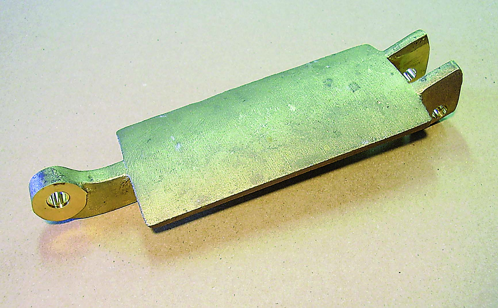
Figure 1
A casting with a curved-surface datum.
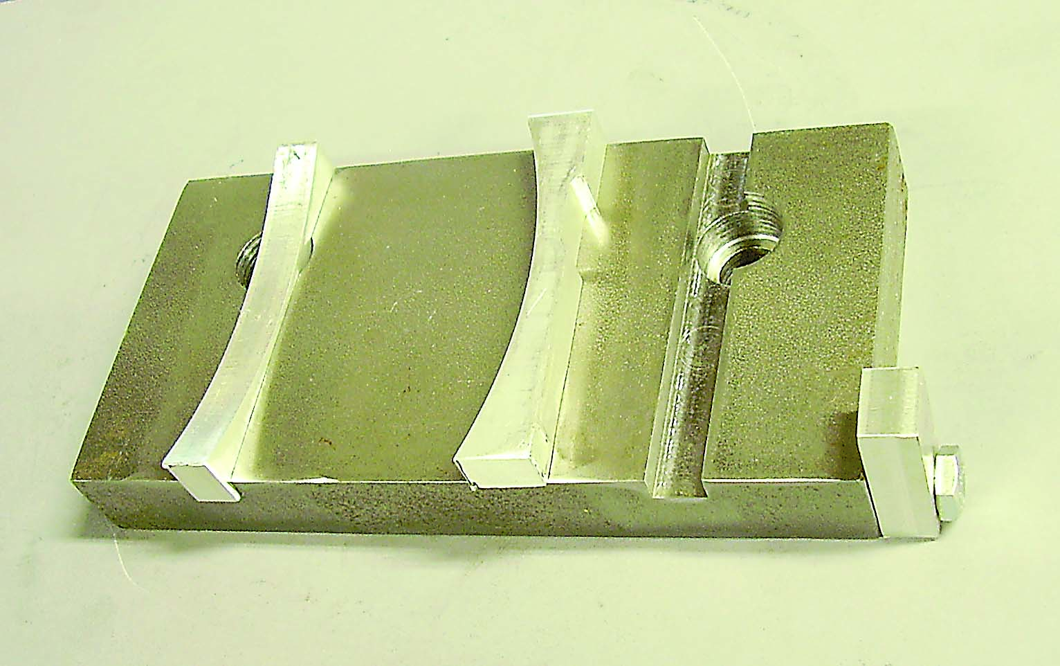
Figure 2
The front jaw with inserts and the work stop.
Therefore, the three struts have an average compression of 0.0635 mm (0.0025″) under the 3,175 kg load, which ensures that all three clamping points are held securely. The 2,758-bar (40,001-psi) yield strength of the aluminum workpiece guarantees that it will withstand the 365-bar (5,294-psi) clamping stress.
To hold the part in the vise, a pair of soft jaws were made from 19 mm × 76.2 mm (0.748″×3″) cold-finished 1018 steel. The front jaw has grooves that accept 9.5 mm-thick (0.374″) aluminum inserts with a 106.4 mm radius. The width tolerance of the casting can be +2.54 mm (+0.1″), so the center of the radius is 39.624 mm (1.56″) above the vise bed. A work stop is attached to one corner of the front jaw with a ¼-20 screw. Figure 2 shows the front jaw with inserts and the work stop.
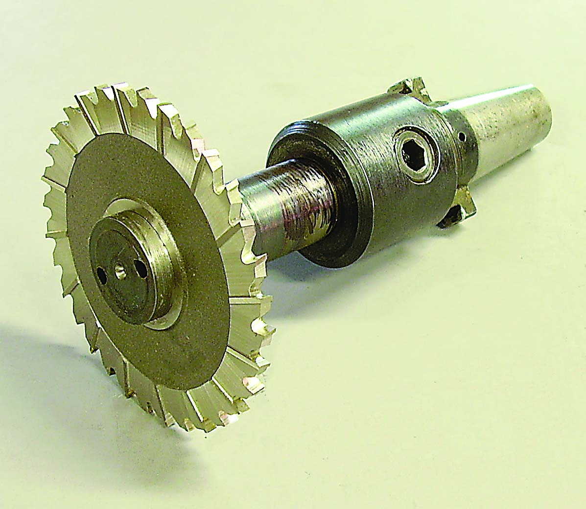
Figure 3
This special toolholder is mounted in an endmill holder.
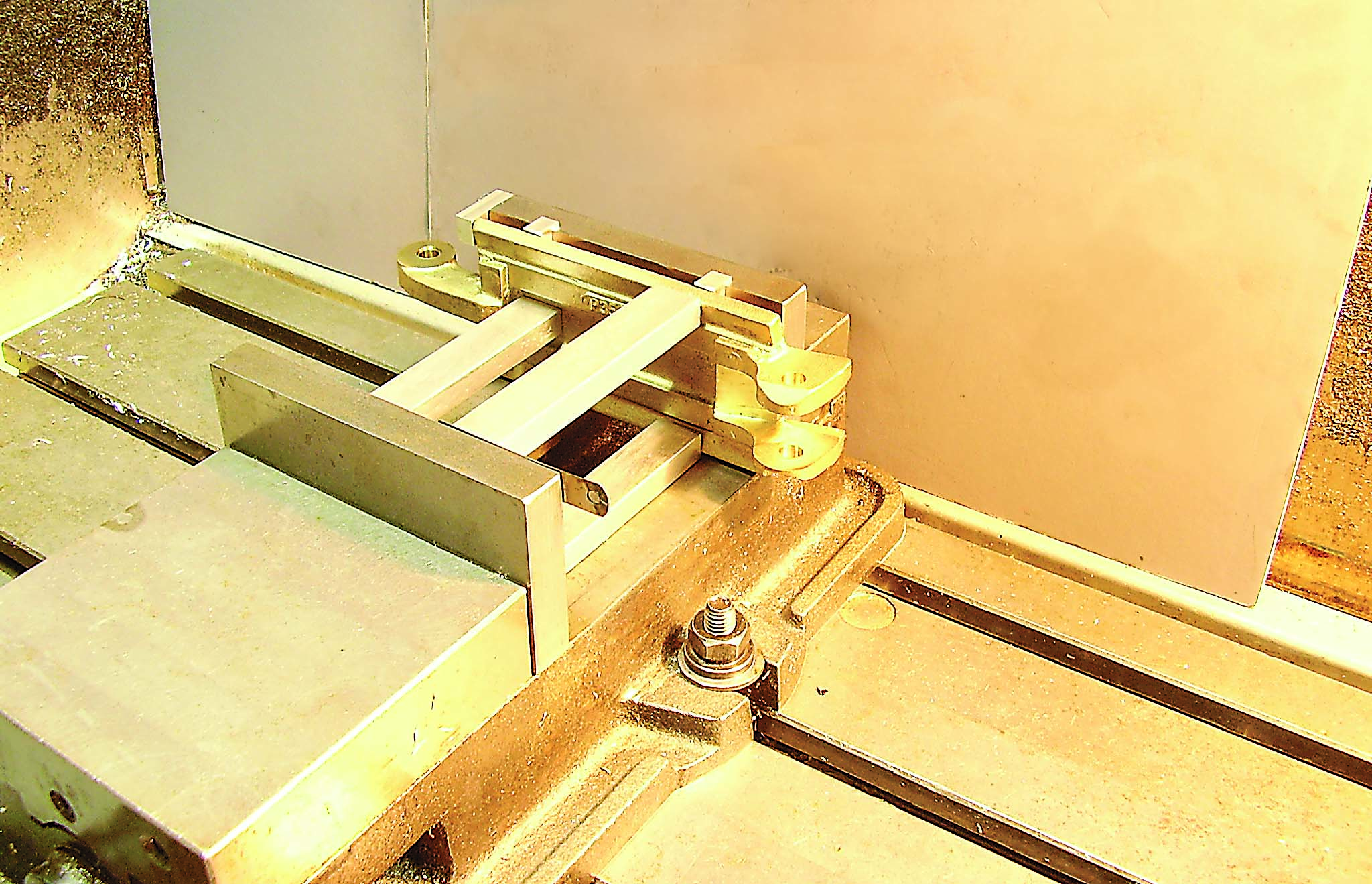
Figure 4
The clamping setup.
A 101.6 mm × 4.8 mm × 25.4 mm (4″×0.189″×1″) side milling cutter was applied to cut the flats. A special toolholder (Figure 3) was made to mount in a 25.4 mm endmill holder.
When using a vise setup with multiple clamping points, ensure that all clamping points are in compression. Workpieces vary in dimensions, which is especially true with castings. Figure 4 shows the clamping setup. To assemble for machining, first put a casting against the front jaw and determine the correct vertical position. Then position the struts, which are held up by spacer blocks. Snug the vise, but don’t tighten it. If a strut is loose, fill the gap between it and the back jaw with a feeler gauge. Then tighten the vise. A bunch of loose feeler gauges work well here.
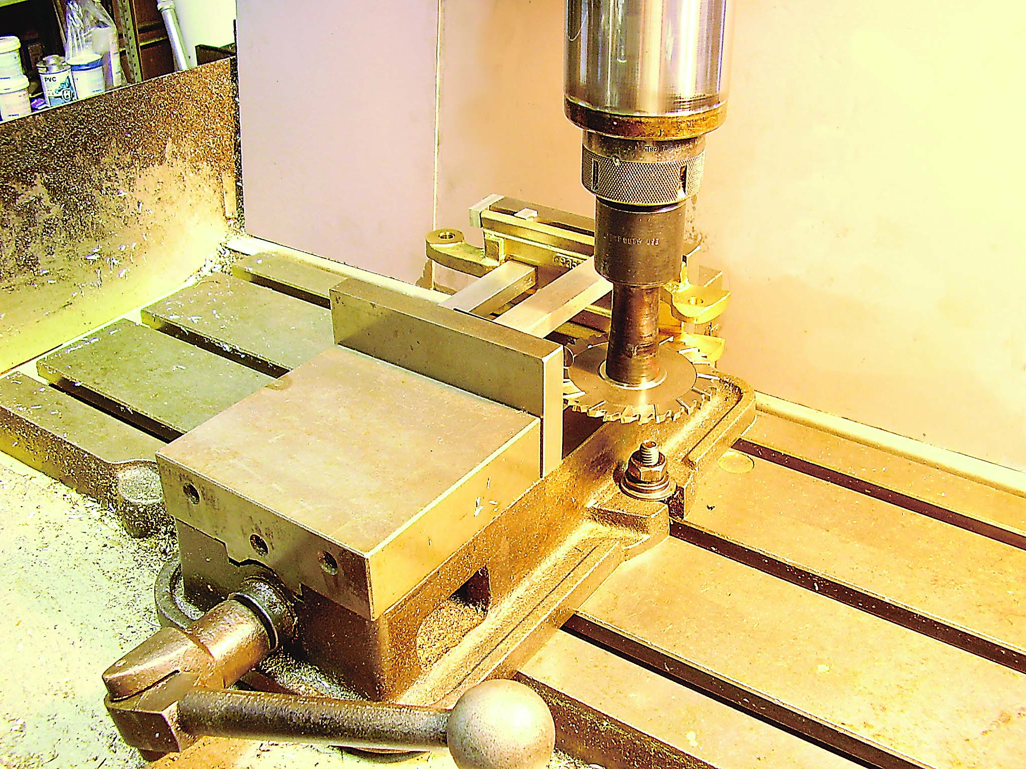
Figure 5
The setup is ready for machining.
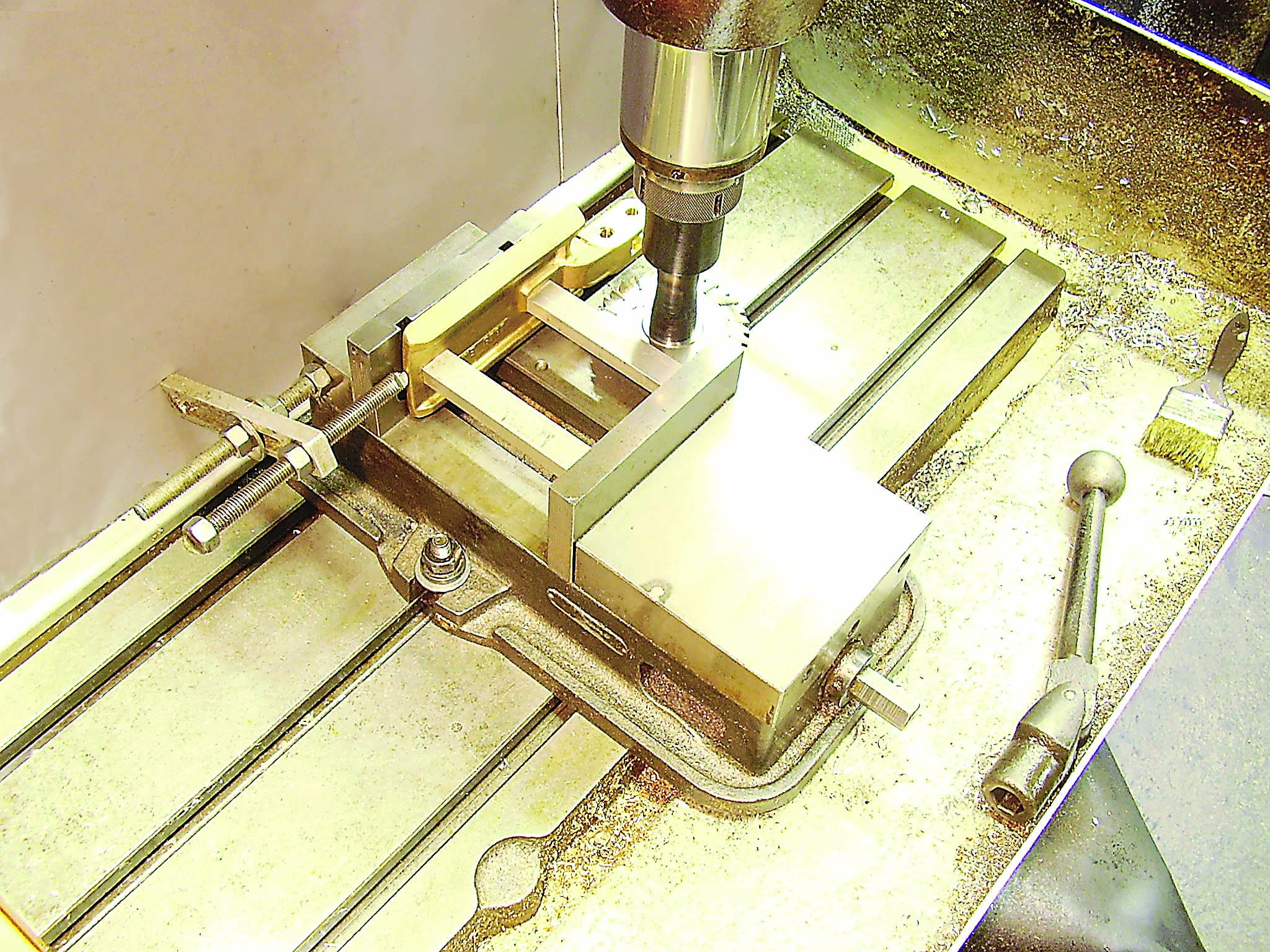
Figure 6
A different casting is machined.
Review the print ads from this magazine to continue
This quick advertiser review unlocks the rest of the article and keeps the full-screen reader focused on the ads instead of the page chrome.


MFGAxis Discussion