Tech swap: 5-Axis Machining
Creating awareness about productivity boosting machining technologies and implementing them are playing a major role in making military parts.
Tool grinder Jim Clark employs the ANCA CNC tool grinding machine at Hamill Manufacturing to create custom geometry on an endmill. Hamill manufactures and modifies tools in-house to maximize efficiency when machining complex parts for military applications.
Creating awareness about productivity-boosting machining technologies and implementing them are playing a major role in making military parts.
Technology transfer is a two-way street. For example, technology NASA developed for space exploration often is adapted by the private sector for terrestrial use, while technological advances made for commercial purposes are being targeted for implementation by the Department of Defense and part manufacturers serving the defense industry. This two-way technology transfer can help increase the nation’s industrial competitiveness, create jobs and improve the balance of trade. In the case of making military parts, the goal of commercial-to-government transfer is to reduce or contain costs by enhancing manufacturing productivity while providing the military with the weapons needed to effectively battle enemies.
One organization helping to facilitate that aim is the National Center for Defense Manufacturing and Machining, Latrobe, Pa. “A lot of the advances in technology come from the commercial sector,” said Ralph Resnick, chief technology officer for NCDMM. “It is up to organizations like NCDMM to help educate the government base on what these commercial processes and technologies are.”

Courtesy of Siemens
The F-35 Lightning II, or Joint Strike Fighter, is one military program that requires advanced manufacturing technologies to efficiently produce all of the needed components.
He noted, however, that because the military needs consistently reliable products, the manufacturing processes for creating those products need to be consistent and validated. That can make implementation of innovative manufacturing solutions a slow process. “The military is very careful about making changes and sometimes this can be a deterrent to change,” Resnick said. “It is the responsibility of organizations like mine to be able to manage that change process and to appropriately transition new capabilities. We need to demonstrate and validate those capabilities so we can get them through the qualification process and subsequently improve manufacturing, which has implications of cost reduction and improved productivity.”
Presented here are several NCDMM projects that implement advanced manufacturing technology, including laser-based measurement, ultrasonic machining and gundrilling.
Out with the Blue
The propulsion drive shafts of Navy submarines, ships and aircraft carriers require maintenance about every 2 years. That involves dry docking the ship or submarine at a Navy shipyard, removing the shaft, inspecting it for wear, filling in any worn areas using additive techniques and then removing excess material on a lathe and with a hand-held grinder. The shafts measure up to 30 ” in diameter and 60 ‘ or more in length. The current method for inspecting a shaft taper, which has been the accepted practice for 50 years, utilizes a bluing fit.
Resnick noted that there are a total of five ring gages used by the U.S. shipyard community for inspecting such large shafts. Each gage weighs 500 to 600 lbs. and is positioned onto a shaft using a sledge hammer with a specific weight and a prescribed number of hammer blows. Then the gage, which has a bluing die applied to its contact surface, is removed and a group of inspectors collectively determine the percentage of bluing transferred from the gage to the shaft, with a good shaft having at least 80 percent of the die. “If the shaft needs additional machining, it’s reinstalled on the machine tool and the process is reiterated,” Resnick said. “It’s very time-consuming and very archaic.”
The inspection process takes about 72 man-hours. “The standard rule of thumb on what are called hotel services, or write-up expenses while in dry dock, is that they cost $250,000 a day minimum,” said Sean Krieger, project engineer with a specialty in repair technology at the Applied Research Laboratory at Penn State. “So the clock is ticking the minute that submarine or ship arrives in the dry dock for refurbishment work.”
The Pearl Harbor Navy Shipyard asked ARL to help improve its metrology processes, including shaft taper inspection. Before that initial project ended, ARL recommended using a Laser Tracker from laser measurement system provider Faro Technologies Inc., Lake Mary, Fla., to do the inspection. Next, NCDMM became involved in the improvement process and concurred that on-machine, laser-measurement assessment of the shafts was an important step forward.
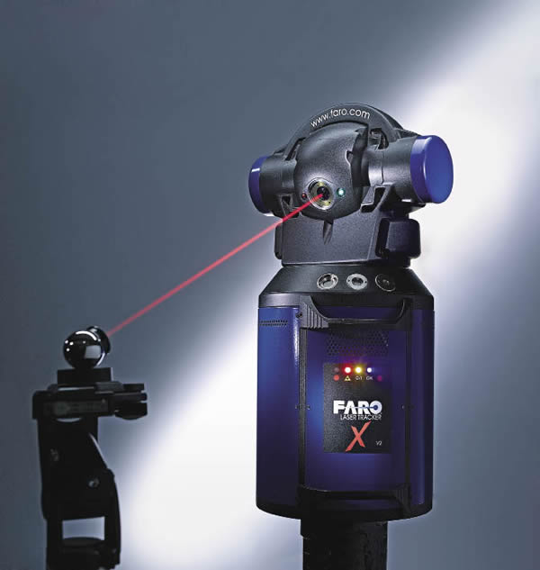
Courtesy of Faro Technologies
A Laser Tracker from Faro Technologies can measure a component, such as a propulsion drive shaft, anywhere and in any orientation.
A Laser Tracker can inspect a shaft anywhere and in any orientation, eliminating the need to remove the shaft from the lathe and position the gage using a crane, according to Chuck Pfeffer, director of product development for Faro, who’s based in Kennett Square, Pa. He explained that to scan the taper section, which measures about 4 ‘ long by 2 ‘ in diameter, an operator first scans half of it from one vantage point by sliding a laser-following probe along the surface of the shaft taper, recording the data as the probe moves, scanning the other side and then tying the two coordinate systems together to provide a single set of scan data. Software, available from multiple developers, allows a user to collect thousands of data points and compare them to a CAD model of the shaft or gage. The software also generates a color map report and a statistical report.
“Pretty much in real time, you can see the data compared to the CAD model on the screen, and analysis tools tell you what percentage is within a certain tolerance to simulate the bluing,” Pfeffer said. “We were trying to get as close a comparison to the gage as we could.”
He added that laser measurement provided a numerical value for the amount of material that would have been interfering with the gage, as well as the gage’s distance from low, worn areas on the shaft. “You didn’t just get a shade of blue, you got a number.”
Laser-based measurement also quickened the machining process. “They tended to take off very little material at a time when they were doing the gage process because they were not that confident in what they were doing based on the feedback from the gage,” Pfeffer said. “With the Laser Tracker, you could take off more material at once, being confident that you knew how much to remove, reducing some of the iterations.”
The prove-out inspections, which were performed at the Norfolk, Portsmouth, Puget Sound and Pearl Harbor Navy Shipyards, determined the proposed Laser Tracker method would take 24 man-hours, saving 48 man-hours per shaft taper. Based on an average shipyard quantity of three shafts per year at each of the six shipyards, the projected 10-year savings equates to $1,962,000, according to NCDMM.
The prove-out process ended March 2008 and the Navy is continuing to evaluate the laser technique. “They double and triple check everything,” Krieger said. “By having outside consultants come in and conduct this evaluation, it opened up their eyes and allowed them to say, ‘Yes, we’ll seriously consider it,’ but it did need to get to a program called ‘cumbersome work practices’ to be fully considered for implementation.”
NCDMM remains optimistic. “We’re hoping that within the next year we will see implementation of the technique,” Resnick said.
Even if the shipyards don’t eliminate use of the ring gage for final inspection, they can still incorporate laser measurement to reduce the total cycle time. “Using it as an in-process tool to get a shaft built right will save most of the time and money,” Pfeffer said, adding that sharing the lessons learned and applying them to other Navy projects would indicate a successful project. “Replacing the gage would be a bonus, but it was very successful for the Navy just to understand what they can use this tool for.”
Machining Composites
There’s usually more than one way to machine part features. That’s the case for tapered cooling holes and seal slots in ceramic matrix composite materials for military aerospace components. CMC is desirable for aerospace applications because it’s a low-weight, high-strength, high temperature-resistant material. However, machining it isn’t so desirable. That’s because CMC is a sintered, dense material that has a laminate structure with four to 12 plies (eight-ply being the most common) and silicon-carbide fibers woven together.
NCDMM has been optimizing machining processes for CMC materials but during an investigation of conventional milling of 0.030 “-wide × 0.150 “- to 0.200 “-deep seal slots for a military aerospace application found that conventional processes took an inordinate amount of time. NCDMM enlisted the assistance of one of its alliance partners, The Ex One Co. LLC, Irwin, Pa., to examine laser and ultrasonic machining of the slots with the equipment the company builds and markets and also uses for its job shop services. Ultrasonic machining uses a vibrating tool to erode the desired shape into the workpiece material.
The time to ultrasonically machine a 3 “-long, 0.150 “-deep, C-shaped slot was 30 minutes, whereas milling required 5 to 10 hours to produce the same slot and consumed five to 10 cutters. “The tooling cost alone was exorbitant but the machining time on top of that was ridiculous,” said Ex One’s Corporate Director of Technology Randy Gilmore.
Drilling cooling holes posed similar problems. Each hole is tapered, having a 0.015 ” diameter for air entry and a 0.025 ” diameter for air exit, to enhance cooling characteristics by enabling air to spread out as it exits the hole and drag more heat away. In addition, the holes are at a 25° angle to the surface of the material for better cooling. Gilmore noted that drilling CMC is a slow process that requires multiple drill bits to complete each hole, and one part may have up to 300 holes.
Ex One was able to laser machine an acceptable hole—no delamination, cracking or fiber or bond coat damage—in about 5 minutes, but only with a laser that provides an ultrashort pulse duration of 10 picoseconds or less. “We also drilled some holes in the nanosecond and millisecond ranges,” Gilmore said. “As we got into those longer pulse durations, we definitely damaged the material.”
Laser machining is not feasible for machining the seal slots because of the difficulty in producing a flat bottom in the slot and—more importantly—the relatively large amount of material that must be removed.
Although ultrasonically drilling a hole takes about 30 minutes, up to 30 ultrasonic tools can be ganged, enabling 30 holes to be drilled in 30 minutes, according to Gilmore. He explained that Ex One’s ultrasonic system incorporates projection machining, where the vibrating tool, called a sonotrode, never touches the workpiece but rather abrasive particles suspended in a liquid are projected across the gap between the tool and workpiece, striking and eroding the negative shape of the tool into the workpiece. The sonotrode vibrates at a nominal frequency of 20 kHz, and the tool tip is vibrating in an amplitude, or stroke, of ±0.001 “. The slurry contains a liquid carrier with abrasive particles suspended in it, as well as lubricants and rust inhibitors because the sonotrodes are typically made of tool steel.
Numerous abrasives are available. For the CMC application, Ex One applied 320-mesh silicon carbide. Gilmore noted that the company used standard ultrasonic machining, which does not damage CMC, but custom tools were needed based on part geometry.
NCDMM stated that with the knowledge gained through the testing of these various machining methods, optimized conventional milling is appropriate for some applications and ultrasonic machining was determined to be applicable for machining tapered cooling holes, seal slots and other part features with similar characteristics. “Because we were able to use the customer’s shapes and materials in our demonstration project on the contract for NCDMM,” Gilmore said, “it was an easy segue for the customer to go directly into utilizing our services to make the actual engine components.” The NCDMM evaluation project has led to subsequent production evaluation contracts for Ex One.
Drilling Deep
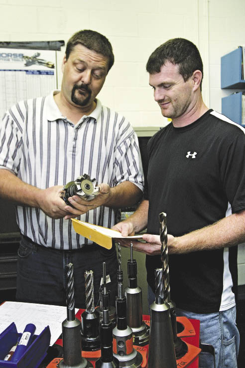
Military parts come in all shapes, sizes and workpiece materials, including thick ones made of difficult-to-machine nickel-base alloys. But that doesn’t necessary mean a new machining technology is needed to produce a difficult-to-machine workpiece. Instead, Hamill Manufacturing Co., Trafford, Pa., needed to identify the appropriate traditional cutting tool to efficiently drill approximately 600 through-holes about 3⁄8 ” in diameter in four 4½ “-thick Inconel heat exchanger components for the Navy. Hole tolerance was ±0.001 “.
The company had experience drilling Inconel up to 2 ” thick and considered drilling and reaming the holes using the same parameters when machining the thicker Inconel parts. However, that meant more than 200 hours to produce each part and if a single hole was out of specification—hopefully not the last one—Hamill would have to scrap the part. “We bid the job knowing it was going to take a long period of time, but it was taking longer than we expected,” said Glenn Skena, manager of methods engineering for Hamill.
Being an NCDMM member, Hamill, which currently produces 60 percent of its parts for the Navy, contacted the center to see if a solution could be found. “We’ve had at least three projects with NCDMM over the years,” Skena said.
Courtesy of Bill Kennedy
Review the print ads from this magazine to continue
This quick advertiser review unlocks the rest of the article and keeps the full-screen reader focused on the ads instead of the page chrome.