



Some measurement required: Research & Innovation
Machine tool users can access the information contained in a stability lobe diagram to greatly increase productivity.
Machine tool users can access the information contained in a stability lobe diagram to greatly increase productivity. My May column demonstrated that by knowing which speed to select and what DOC is permissible, it is often possible to improve productivity by a factor of four or more. No tooling or machine changes are required, just a knowledge of the right cutting conditions expressed on a stability lobe diagram.
As long as the setup is repeatable, the stability lobe diagram is repeatable, and the best cutting conditions can be selected with no guesswork. When milling, some of the required pieces of information are relatively easy to obtain or are already known.
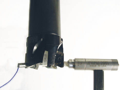
Impact excitation is used to measure a frequency response function. Image courtesy of BlueSwarf Manufacturing Laboratories, State College, Pa.
You need to know a specific material property called the cutting force coefficient. The cutting force coefficient relates the chip area to the cutting force. This coefficient is also sometimes called the specific power because it relates power to the metal-removal rate. This data is tabulated for many common workpiece materials. (See “Machining Dynamics—Frequency Response to Improved Productivity,” by Schmitz and Smith, published by Springer.) As an example, Aluminum7075-T6 is about 850 N/mm2, which corresponds to about 0.3 hp per in.3/min.
You also need to know how many teeth are on the tool because that factor changes the location of stable pockets in the stability lobe diagram.
In addition, you need to know the radial DOC. A safe choice is to assume full slotting because that sometimes happens in corners, and full slotting provides the smallest permissible axial DOC. If you are stable in a slot, you are stable at other radial immersions, too.
One other needed piece of information is more difficult to obtain—the frequency response function (FRF). If you apply a force to the tip of a cutting tool via machining, the tool deflects. The relationship between force and deflection is called stiffness. However, the force from cutting is rarely constant and the resulting deflection also depends on the frequency of the force. There are particular frequencies (natural frequencies) where the deflection is large compared to the force.
By way of analogy, if you have driven a car with an unbalanced wheel, you know there is a particular speed at which the vibration of the car is quite large. The FRF is a measurement of this characteristic and is different for every tool in every machine. The same tool measured in two different machines may have a completely different appearance. The FRF is the one item needed for the stability lobe diagram that is specific to your setup.
Impact excitation—a simple technique that measures FRF—requires hitting the tool tip with an instrumented hammer. Really. The hammer has a sensor that measures the force when hitting the tool. The photo shows an impact test on a facemill. An accelerometer is attached to the tool, shown on the left side of the image. The accelerometer measures how the tool vibrates in response to being hit.
The hammer and accelerometer are attached to a data acquisition computer, and software establishes the frequency-dependant relationship between the force and the displacement—the FRF. The measurement equipment, hardware and software have been commercially packaged, for example, by Manufacturing Laboratories Inc., Las Vegas, in the company’s MetalMax kit. There are different sizes of hammers and accelerometers, depending on tool size.
The accelerometer is attached to the tool using sticky wax, glue or magnets. Some training is required to learn the technique. Dr. Tom Delio, president of MLI, said, “If you can swing a hammer and run a Windows-based PC, you can learn to make this measurement. Most people pick it up in an hour or two.”
The calculation that converts the required information into the stability lobe diagram is automated in MLI’s software. The calculation details are described, for example, in “Manufacturing Processes and Equipment,” by Tlusty, published by Prentice Hall; or “Metal Cutting Theory and Practice,” by Stephenson and Agapiou, published by CRC.
The measurement of an FRF and the calculation and use of a stability lobe diagram were once relegated to university laboratories and large corporate R&D centers. However, in recent years this technology has become available for use on the shop floor. The productivity gains a stability lobe diagram enables are often quite large—a competitive advantage that may be too big to be ignored. CTE
About the Author: Dr. Scott Smith is a professor at the William States Lee College of Engineering, University of North Carolina at Charlotte, specializing in machine tool structural dynamics. Contact him via e-mail at kssmith@uncc.edu.
Glossary terms in this article
Related




Subscribers can use MFGAxis notes, saves and discussion tools with their innoNET account.


