



Composite Connection: Drilling Performance
Abrasive waterjet cutting has grown along with the increased use of composites in airframes, and advanced techniques help make it a preferred technology.
The use of carbon-fiber composites is increasing as a structural material for commercial airframes. This material represents 90 percent by volume of the new Boeing 787 and Airbus 350XWB airframes.
The abrasive waterjet has become the tool of choice for trimming and shape cutting this material due to technical, environmental and economic advantages. AWJ cuts impart an acceptable surface finish and material-removal rates are higher than conventional routing. Significant advances have been made in AWJ hardware, software and process reliability, making it a highly productive, mainstream tool for airframe manufacturers and their subcontractors.
All images courtesy of Flow International
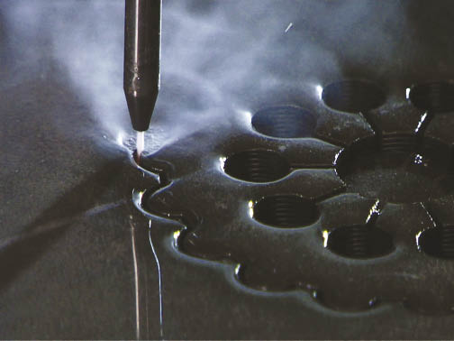
An abrasive waterjet cutting a composite material
The use of advanced materials such as composites has been escalating rapidly over the past 30 years, especially in the aerospace industry—coincident with the introduction of AWJ technology in the 1980s. In fact, aerospace applications have been a primary driver in the growth of waterjet technology. This article briefly discusses AWJ hardware and software and their use in trimming and drilling carbon-fiber composites.
Composite Systems
Organic, metal and ceramic matrix composites (OMCs, MMCs and CMCs) are used in jet engine and airframe components. In jet engines, for example, the engine’s cold section includes OMCs, MMCs and intermetallics. OMC components may include fan frames, fan blades, inlet and outlet guide vanes, stator vanes, cases and control housings.
Another composite, Graphite-PMR-15, is used for structural parts on such engines as the GE F110 and F404 and the Pratt & Whitney 1120 and 1130. (PMR stands for in-situ polymerization of monomer reactants.) Hot sections such as combustors, turbines and exhaust sections require the high-temperature capabilities of intermetallics, single-crystal superalloys, CMCs and carbon/carbon composites.
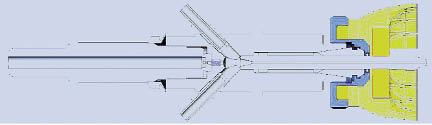
Figure 1: AWJ cutting head with vacuum assist. One port is for abrasive feed and the other for attaching a vacuum device.
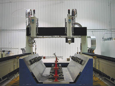
Figure 2: A hybrid waterjet system, with waterjet on the left and the router on the right.
OMCs—especially carbon fiber-based composites for aero structures—were initially used on military airframes and have since been extended to commercial aircraft. Example parts include:
• Wings: covers, spars, leading edges, flaps
• Fuselage: panels, stringers, frames, clips, doors
• Tail: VTP and HTP covers, rudder and flaps
• Other sections: keel beam, center wing box, belly fairing
Aircraft and their AWJ-machined components include:
• Boeing 787: center wing box, wing skins, spars, stringers, fixed leading edge, vertical stabilizer
• Boeing 777: horizontal stabilizer
• Boeing 747: titanium landing gear components
• Airbus 350XWB: wing spars
• Bell Helicopter V-22 Osprey: wing skins, stiff rotors
• Raytheon Premier I: fuselage
The Boeing 787 and the Airbus A350XWB will make the most revolutionary use of composites, having 50 percent composite structure by weight and 90 percent by volume. By comparison, the Boeing 777, which entered service just over 10 years ago, contains only 10 percent composite structure by weight. The U.S. Army’s new F-35 Lightning II (Joint Strike Fighter), expected to enter service in 2010, will have about 40 percent composite structure by weight, using titanium-graphite (TiGr) laminates. The F-22 Raptor, which entered service in 2003, has approximately 25 percent composite structure by weight.
Typical problems that have been encountered when machining carbon-fiber composites with conventional solid-carbide tools are matrix cracking, fiber pullout, interlaminar voids, delamination and resin melting. These problems leave frayed or otherwise damaged edges, which require costly rework and slow down production cycles. Frequent tool changes are required when applying routers or drills due to composite’s abrasive nature. Solid tools generate dust and carbon powder when machining composites. If this dust becomes airborne, it can wreak havoc on electrical systems and create an unhealthy work environment.
The growing use of composite materials in primary aircraft structures requires technology that reduces manufacturing and tooling costs and the potential for product defects. AWJ technology offers several advantages over conventional machining methods for 2-D and 3-D machining of composite structures:
• No distortion due to limited waterjet forces
• No heat-affected zones
• Reduced demand for fixturing and tooling
• No delamination
• No subsequent processes required
• No splintering or fraying edges
• Process automation and multiple operations are possible
• No dust
AWJ Technology Advances
Advances in AWJ machining of composites for airframes can be grouped into two basic categories: machinery (hardware) and software.
Cutting heads: The use of vacuum assist in AWJ cutting heads (Figure 1) has been critical for successful shape cutting of composites. An external vacuum source draws abrasives into the cutting head before starting the waterjet, ensuring its instantaneous firing. Delamination does not occur when piercing composites using this approach. The vacuum assist is particularly important when lower pressures around 10,000 psi are used, as is often the case when piercing composites. In this case, the waterjet venturi effect is not sufficient to draw abrasives reliably into the cutting head, so vacuum assist enhances AWJ process reliability.
Hybrid waterjet systems: To trim and rout composites, both waterjets and solid-tool routers have been incorporated on special hybrid systems (Figure 2). These systems have two 5-axis masts: one for the AWJ and another for the router. The AWJ trims the part using an end effector. A small catcher is provided on a 6th axis for catching the exit jet and directing the waste outside of the wrist area to the collection tank. The router drills and countersinks the required holes or trims critical areas not easy to address with the AWJ. A hybrid system helps minimize setup time. Hybrid machines range from 10 ‘ to 150 ‘ in length with widths up to 50 ‘. Probing and linear scales are used to obtain required accuracy.
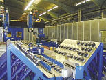
Figure 3: A fixture for holding curved parts.
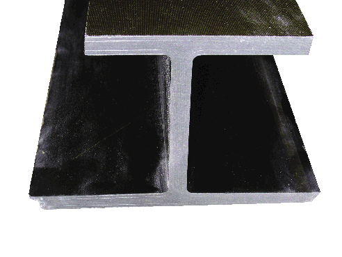
Figure 4. A composite stringer.
Flexible fixturing: This is a key component in AWJ machining cells due to the variety of shapes and contours of airframe parts. Flow International has developed fixtures consisting of a number of linear actuators with vacuum cups, as well as hard location surfaces and points for accurately locating the part and rigidly holding it during cutting. The fixture must also allow the jet to be effective after it has penetrated the material and accommodate a catcher, if needed. Figure 3 shows a fixture for holding curved parts that may be used in fuselage sections.
Software: Most airframe parts are designed with CATIA solid-modeling software. To develop a CNC program for trimming and drilling parts, a post-processor program is needed to translate the drawing so that the machine controller can execute it. This post-processor also includes information about the process, such as cutting speed and tool diameters. This is a critical element of AWJ machining because most parts have complex 3-D shapes. Flow International and CINET Systems developed FlowTrim: CAD (for data import, part design, fixtures and runoff material) and CAM (for programming, simulation and toolpath modification) as an integrated post-processor using integrated cutting technology models and data tables.
Waterjet Processes
Common airframe waterjet processes are trimming, shape cutting and drilling. Trimming is typically performed on the edges while shape cutting is performed on interior surfaces to produce openings such as access holes or windows.
There have been significant advances in the use of nonabrasive and abrasive waterjetting for composite part trimming, which is required because parts are typically oversized due to the composite manufacturing process. A wide plateau of parameters has been found to be acceptable for cutting sections of graphite epoxy with thicknesses from 0.1 ” to 3 “. Surface quality finer than 400µin. Ra (as typically specified by Boeing) can be achieved at relatively high productivity levels. For example, a cutting speed of 20 ipm can be used to trim 0.35 “-thick carbon-fiber using a 0.010 “-dia. AWJ at 55 ksi (one ksi is equal to 1,000 psi).
Some edges may be trimmed at bevel angles, and when cutting around curves and complex contours, the effective depth of jet cutting varies. As a result, waterjet kinematic parameters such as speed and angles must be carefully programmed to maintain uniform edge quality. Trimming I-beam (stringer) composites requires special tooling such as catchers and cutting heads. Figure 4 shows a stringer cross section with the top flange trimmed at 90° with an AWJ. The bottom flanges show the condition of the edge before trimming. The top and bottom flanges are shaped and trimmed with the ends trimmed to the center rib or close to it. Also, the bottom flange needs to be beveled at about 45°. Some access holes are also drilled in the rib. Because these stringers are long (the ones used in wings are more than 130 ‘), they require special workholding during cutting.
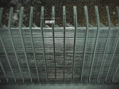
Figure 5: AWJ cuts in thick composite section.
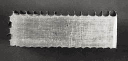
Figure 6. Bottom surface of 25-mm thick honeycomb cut using an AWJ with and without a 9° lead angle.
Shape cutting requires a starting hole. Some systems use a mechanical drill to predrill the starting holes but more often AWJ is used to drill these holes as part of the shape-cutting sequence. In this case, vacuum-assist nozzles mitigate the risk of delamination. To cut near the bottom flange, a special AWJ nozzle less than 1.5 ” in total size is used.
While the majority of AWJ trimming applications address relatively thin sections (less than 0.75 “), there are several thick-section cutting applications (up to 3 “) near the wing-to-fuselage joining areas. Figure 5 shows an example of cuts in thick composite sections that can be made faster with AWJ using simpler fixtures and less heavy equipment than with mechanical tools.
The end trimming of composite stringers is another application that requires a 5-axis manipulation strategy to avoid exit-jet damage on the opposite sides of the stringer. A feed rate of 1 ipm can be used to cut a 3 “-thick section while producing an acceptable 400µin. Ra surface finish.
One challenging application is cutting composite honeycomb structures because the cutting path is not continuous. A cut at the bottom of a honeycomb structure appears as a series of punched holes. Cutting at a lead angle of about 9° has been found effective for minimizing this effect (Figure 6).
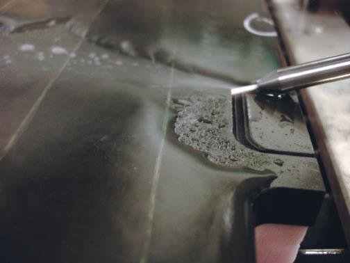
An angle being cut in a composite wing stringer.
Drilling (piercing): Delamination is the main failure mode when drilling materials such as graphite epoxy with waterjets, but it can be resolved using vacuum assist and proper cutting parameters. Thousands of holes have been drilled in carbon-fiber composites without any adverse effects. With proper process timing, holes can be drilled rapidly. While not as fast as laser machining, waterjetted holes are typically of high integrity and have good surface finish. The AWJ process has been successfully investigated for rapid drilling (piercing) of holes in composites. For example, Figure 7 illustrates the drilling of 0.40 “-dia. holes in a 0.040 “-thick composite material. Drilling time was about 0.9 seconds hole-to-hole.
Pierced hole size can be controlled by selecting process parameters and dwell time. The longer the dwell time, the larger the final exit hole size. Accurate control over the dwell time is needed to control hole-size tolerance. Another interesting observation is that drilling time is reduced by reducing the water flow rate and increasing the abrasive flow rate into the hole.
Emerging Applications
Turning of composite materials results in significant problems when using traditional turning and grinding techniques due to the multidirectionality of the composite lay-up and its abrasiveness. OMCs are typically not turned to produce parts, but AWJ’s ability to turn these materials may lead to the development of new structures. AWJ turning is performed by rotating the workpiece, as in the case of a lathe, and then traversing the waterjet to produce the required contour.
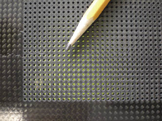
Figure 7: AWJ-drilled holes in a carbon-fiber composite panel.
The AWJ milling process is conducted by traversing the jets with many passes close to each other across the workpiece surface. Multiple passes of overlapping kerfs are used to achieve controlled depth. The milling of isogrid shapes in graphite epoxy was conducted to demonstrate the degree to which milling depth can be controlled. This approach involved the use of steel masks. It was found that depth control can be as accurate as 0.001 “. The material can be milled ply-by-ply if needed, suggesting its potential for repair applications
In the repair application, damaged material is first removed and then patched to the original geometry. The flexibility of AWJ cutting in a range of materials and shapes makes it suitable for repairing composite structures. Alternatively, AWJ can be used for milling off the damaged section or preparing the patch. For example, the AWJ can be robotically scanned over the surface, producing a scarfed geometry suitable for repair.
The AWJ process has become a mainstream process for composite trimming. While improved fixturing, cutting heads and end effectors are still needed to develop additional part geometries and sizes, advances in processes, machinery and software have made AWJ an essential tool for the aircraft industry. Today, all airframe manufacturers—aided by new software and offline programming—accept and readily use AWJ for trimming composites. CTE
About the Author: Mohamed Hashish is senior vice president, technology, with Flow International Corp., Kent, Wash. For more information about the company’s waterjet systems, call (800) 446-FLOW, visit www.flowcorp.com or enter #340 on the IS Card.
Related Reading
- Related guide: Composite.
Glossary terms in this article
Related




Subscribers can use MFGAxis notes, saves and discussion tools with their innoNET account.


