Tough Bores: Drilling Performance
This article relates how three shops used creative ideas to solve difficult boring problems. One shop built a custom tool to bore deep holes. Another used a combination of standard tools to bore an interrupted cut. And a third achieved tight tolerances with an assortment of plastic sleeves and plugs.
If you’re a production engineer or machinist, you probably cringe at the thought of producing parts that involve certain types of machining operations. And that’s OK. After all, you’re the one responsible for ensuring that these parts are machined correctly and cost-effectively.
A lot of people find it challenging to machine accurate bores at a reasonable cost. Among the obstacles that must be overcome are tool deflection and vibration, as well as boring-tool selection, which is limited by the hole’s diameter and length. Further ratcheting up the challenge is the fact that bore tolerances are usually very tight.
Despite these hurdles, certain shops seem to thrive on finding solutions to tough boring problems. CUTTING TOOL ENGINEERING highlights three of them in the following pages.
Tipping the Scale
Randy Schuster is the production manager of PSC Machining and Engineering Inc., an East Chicago, Ind., contract machine shop. PSC supplies one of its customers, a steel producer, with a family of caster rolls used on steel-processing machines.
The caster rolls are made of centrifugal-cast 420 stainless steel (Figure 1). Through-hole lengths vary from 12″ to 24″. The center hole accommodates an axle that supports the roll.
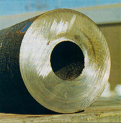
Figure 1: PSC makes caster rolls from 420 stainless steel. Removing the scale from the parts’ IDs initially proved to be a “boring nightmare.”
The customer asked PSC to clean up the scale left in the caster rolls’ center holes. Scale remnants from the casting process were contaminating the grease that coated the axle and were entering the axle’s bearings.
Schuster agreed to do the job, quoting $18 per part for the 50-piece order that he had on the floor. He assumed that the task would be fairly simple. It quickly turned into a boring nightmare.
First, Schuster had shop personnel try to remove the scale by widening the center hole from 2.20″ to 2.25″ with a cobalt-HSS spade drill coated with titanium nitride. There was just one problem: Centrifugal-cast stainless steel is not easy to drill. The material to be removed had a hardness of RC 30 to 33. The flanks of the drill wore out almost immediately upon entering the part.
Schuster then approached a local shop that specializes in drilling deep holes in tough materials. It wanted $50 per part, which meant PSC would lose money on the job. Schuster had to get creative—fast.
Boring seemed like a logical choice. Using a boring bar mounted on a Mazak Slant 50 CNC lathe, PSC bored half of the first caster roll’s required length. The part, which weighed about 140 lbs., was then unchucked, turned around, rechucked and bored from the other end. The combination of hardness, part deflection and weight required three boring passes at each end. Total cycle time was 25 minutes.
At $18 per part, the job was costing PSC $30 in cycle time alone. Plus, tool costs were out of line because inserts were burning up in a single pass.
After some brainstorming and scrounging around the shop, Schuster came up with a new plan: Devise a tool/toolholder system that would be long enough to machine the bore in one pass. The tool portion of the system was a 2.25″-dia., HSS ballnose endmill. The toolholder was an old Beaver Rapid quick-change holder with a No. 5 Morse taper (Figure 2).
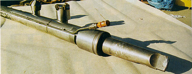
Figure 2: Using an old Beaver Rapid toolholder, PSC built its own extended holder to machine the bore in one pass.
PSC turned a 26″-long piece of heat-treated 4140 steel until its diameter was 2.50″—roughly 0.002″ to 0.003″ larger than the holder’s inner diameter. The shop heated the holder and inserted the bar into it. Then PSC drilled and reamed two setscrew holes at the boring end of the bar and tightened the endmill in place with setscrews.
The first pass with the “new” boring system went nowhere. Almost as soon as the lathe fed the endmill into the bore, it burned up. Schuster discovered that coolant discharged from the turret fitting was not reaching the cutting zone and, therefore, was not dissipating heat.
He decided to mill a slot the length of the holder and solder a standard automobile brake-line tube into it. This delivered ample coolant to the cutting edge, but the next endmill bored just 4″ before failing.
A harder cutting edge seemed to be the answer. Schuster thought that a facemill with carbide inserts might do the trick. But he couldn’t find a standard facemill/insert combination that would fit the bore. And a custom tool would take weeks—well past the scheduled delivery date for the caster rolls.
Then a PSC machinist volunteered to become a weekend toolmaker. Using a commercial indexable facemill as a guide, he fashioned a tool on the Bridgeport milling machine at his home. It accepted three 3/4″-dia., button-shaped, TiN-coated carbide inserts (Figure 3). Though not overly sophisticated, the tool worked.
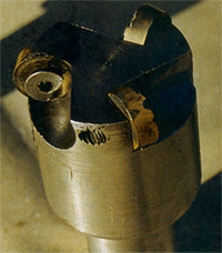
Figure 3: One of PSC’s machinists made a facemill that allows boring to the correct diameter in a single pass.
Running at a speed of 120 sfm and a feed rate of 0.020 ipr, the tool completed a 12″-long bore in a single pass. Problems associated with heat buildup, however, required the operator to index the inserts after each pass. So the speed was dropped to 70 sfm and the feed was increased to 0.038 ipr. At these parameters, the tool completed three to five parts before indexing was necessary.
Schuster refined the process further. He had a second facemill made, allowing inserts to be changed offline. Also, operators now bore the first 1″ of the hole with a standard boring bar. This provides the same advantage as a spot drill: minimizing deflection from the centerline. A third refinement was to add a steady rest, which provides extra support for the part.
The only drawback to the tool is the 1/4″ socket-head cap screws used to hold the inserts. Coolant pushes chips into the screws, causing them to wear rapidly. While the screws must be replaced as frequently as the inserts, the tool is still very cost-effective. It bores at 3 to 5 ipm and averages six pieces per hour.
Schuster estimated that his total nonperishable investment was about $500. That small outlay let PSC go from losing a lot of money per part to making a little. But, more importantly, it allowed the company to meet the needs of a valuable customer.
‘Heart’ of the Matter
When machinists utter “precision boring” and “interrupted cuts” in the same sentence, it usually means that they’re talking about challenging machining operations.
Schmiede Corp., Tullahoma, Tenn., manufactures a gear pump body used in injection-mold machines. The part, made of prehardened 4340 steel, has two parallel, overlapping bores intersected by a cross hole. The cross hole, which is also bored, creates a heart-shaped edge between the parallel bores (Figure 4).
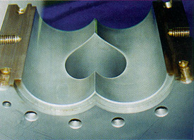
Figure 4: Cutaway of the gear pump housing shows how the three bores intersect to create a heart-shaped edge.
This shape requires the tool to make interrupted cuts while maintaining a diametrical tolerance of ±0.0002″ in each bore. The true-position tolerance between the bores is also ±0.0002″. In previous boring operations Schmiede performed, tolerances were held to ±0.0010″.
The company considered ID-grinding the three 8″-deep bores, but decided it would be too expensive. So it opted for a combination of standard tools made by KPT Kaiser Precision Tooling Inc., Elk Grove Village, Ill. (Figure 5).
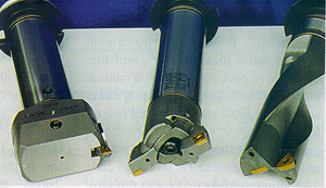
Figure 5: Schmiede solved its boring problem by using a combination of standard tools.
Schmiede starts by drilling the parallel holes with a 2.5″-dia. indexable drill fitted with TN-15-grade inserts made from C-6 carbide. The inserts have three coatings: titanium carbide on the substrate, a middle layer of aluminum oxide and a top layer of TiN. The drill is run at a speed of 500 sfm and a feed of 0.005 ipr.
At this point in the production process, the holes are parallel but do not overlap. Next, a set of three modular, twin-cutter boring-head tools rough-bore the parallel holes. Each tool removes 0.50″ of stock, widening each hole’s diameter to 4.075″. During this phase, the interrupted cuttting begins as the boring head starts to break through the wall of material that separates the two holes.
Jack Burley, product manager for KPT, explained that the two inserts in each boring head are offset 0.010″ from one another. This technique, called “step cutting,” increases the metal-removal rate, results in the production of thinner chips and requires less spindle horsepower than using a single insert.
The boring-head inserts are a TNP-11 grade made from C-7 carbide. Titanium carbonitride is bonded to the substrate, followed by a layer of Al2O3 and an outer coating of TiN. The first pass is made at a speed of 500 sfm and a feed of 0.007 ipr. For the next two passes, the feed remains the same while the spindle speed drops to 538 and 470 rpm, respectively.
The next step is to drill the cross hole with the 2.50″-dia. indexable drill. The cross hole is then rough-bored in three passes to a 4.075″ diameter, in the same manner as the parallel bores.
The finish diameter of all the bores is 4.0906″ (±0.0002″). The remaining 0.0156″ of stock is removed using a KPT high-precision boring head. It is equipped with a micro-adjustment feature, allowing the diameter to be changed in 0.0005″ increments without dial indicators or special presetters. A cermet insert makes the finishing pass at a speed of 670 sfm and a feed of 0.004 ipr.
The combination of boring tools lets Schmiede meet the finish requirement of 20 rms without grinding.
Thin Margin for Error
MRI (Magnetic Resonance Imaging) machines incorporate cryogenic pumps that contain cylindrical flanges like the one shown in Figure 6, which is manufactured by DPI Inc., Southampton, Pa. The part begins as a 65-lb. slug of 304 stainless steel that is 5.25″ in diameter and 10.20″ long. When finished, it has an overall length of 9.911″; its flange portion is 1.60″ long and has a 4.95″ diameter.
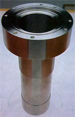
Figure 6: DPI Inc. bores this cylindrical flange, which has three wall thicknesses: 0.120″, 0.037″ and 0.070″.
The part’s tube section has three wall thicknesses: 0.120″ near the flange, 0.037″ at the center and 0.070″ at the end opposite the flange. The bore diameter has a tolerance of ±0.002″, and the finish requirement is 16 rms.
The outer diameter of the cylinder must be turned carefully, because of the thin-wall sections and the very tight OD dimensions. The TIR of the cylinder OD cannot exceed 0.004″. Each cylinder section must remain parallel within 0.001″, and the perpendicularity (with respect to the tube centerline) must be within 0.003″. Cylindricity must be held under 0.0005″ over the entire OD of the tube.
DPI’s lathe supervisor, Tom Tiver, explained the machining steps required to produce the part. First, the slug is rough-profiled using a Kennametal 15º lead-angle toolholder and a Toshiba Tungaloy 55º T335S insert that has a carbide substrate and a TiN/Al2O3 coating. The rough-profiling operation leaves a layer of stock 0.025″ thick, which is removed during a second roughing pass and the final finishing operation.
Next, the flange-side bore is roughed with a T335S insert that has an 80º geometry. The part is rough-bored to a depth of 5″. It is then unchucked, turned around, rechucked and bored from the opposite end. Again, 0.025″ of stock is left for subsequent operations.
After the flange’s mounting holes are drilled and tapped on a vertical machining center, the rough part returns for final boring and turning. A 5″-dia. aluminum sleeve is slid over the cylinder section. Sandwiched between it and the cylinder OD is a plastic tube. The plastic tube dampens vibration and facilitates a consistent finish.
The part is chucked with soft jaws on the side opposite the flange. The jaws support most of the OD, which minimizes the chances of the bore collapsing, maximizes the pressure needed to prevent deflection and helps maintain the 0.0005″ cylindricity tolerance.
The OD of the flange is then finish-turned, and the flange-end grooves and chamfers are machined. A second roughing pass is made on the flange-side bore with the same 80° insert used for the first boring pass. The second pass leaves 0.004″ to 0.005″ of finish stock.
A Tungaloy AH120 80° insert with a TiN/Al2O3 coating performs the final boring pass. The 5″ flange-side bore depth must meet a diametrical tolerance of ±0.0010″. Perpendicularity cannot deviate more than 0.0030″, and the cylindricity over the 5″ section cannot exceed 0.0005″. The finish pass is made at a speed of 250 sfm and a feed rate of 0.004 ipr.
The part is then unchucked, turned around and rechucked at its flange end. The aluminum/plastic sleeve remains on the cylinder to provide rigidity and dampen vibration. The roughing and finishing passes are now completed on the backside bore in the same manner as they were on the flange-side bore.
The tolerance on the second side does not include a specific cylindricity tolerance, but DPI must still maintain a diametrical tolerance of ±0.0010″ over the entire backside bore. Tiver said that DPI is able to consistently limit the “edge”—the area where the two bores meet—to less than 0.0005”.
Next, the aluminum/plastic sleeve is removed and a 9″-long plastic plug is inserted into the bore. This serves to dampen vibration and prevent deflection of the thin-wall sections during final OD profiling. The second OD roughing operation is accomplished with the 55° T335S insert. The finish stock of 0.004″ to 0.005″ is removed with a second AH120 insert that also has a 55° geometry. Running at 350 sfm and 0.006 ipr, the insert leaves the required 16-rms finish. DPI machines the bores on a Hitachi Seiki 25G 2-axis lathe with conversational programming.
DPI has been making the cylindrical flanges in 50-piece lots for about a year now—a total of 450 parts. According to the company’s president, Jeff Wolf, the process is extremely consistent. He reported that only three of the 450 pieces were out of tolerance. They were off so slightly, though, that the customer accepted them anyway.
DPI demonstrates that gaining control over every aspect of the boring process is the key to consistency. DPI also shows, along with the other companies featured in this article, that even the toughest of boring problems can be solved.


MFGAxis Discussion