

Look Ahead: a novel 3D-connector inspection system
G2 Technologies has developed a customizable, automated 3D inspection system in response to a customer's need to inspect small electronic connectors. This niche is very specific, but impacts aerospace, automotive and other industries. The global market for the connectors industry is projected to reach $80.3 billion by 2022, according to G2.
G2 Technologies has developed a customizable, automated 3D inspection system in response to a customer’s need to inspect small electronic connectors. This niche is very specific, but impacts aerospace, automotive and other industries. The global market for the connectors industry is projected to reach $80.3 billion by 2022, according to G2.
The company’s new 3D system combines a vision-based, noncontact 3D inspection system with cleaning, electrical test and engraving stations. The system has the flexibility to inspect a variety of connectors, with pin counts ranging from four to 32. It can deliver one-cycle rolling changeovers between parts and achieve a 3.5-second takt time (the maximum allowable time to produce a part to meet customer demand) on each part, according to the company.
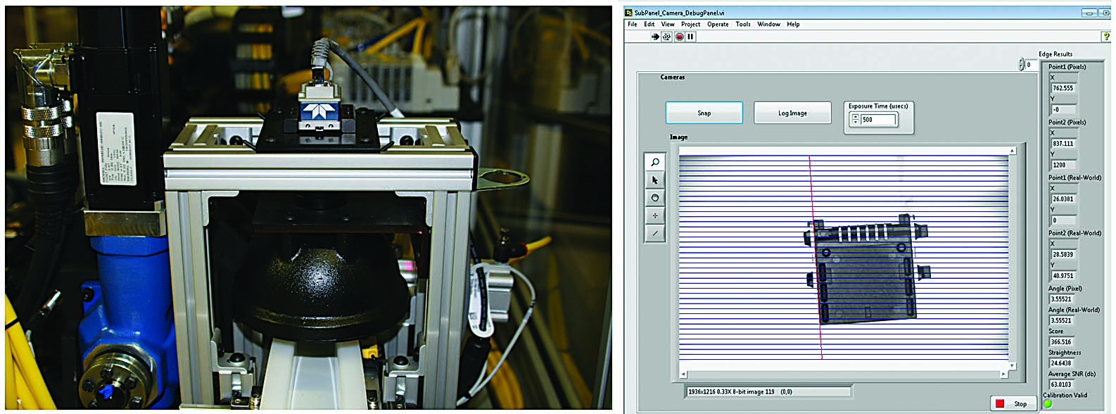
Before connectors enter the 3D vision system for board-side scanning, they are inspected to verify that the correct part is present and that it’s in the proper orientation. Image courtesy of G2 Technologies.
The 3D connector inspection system is installed after “stitching,” a process that accumulates contact pins and inserts them into molded connector housings. Stitched connectors enter on an input conveyorand pass under a Teledyne DALSA Genie Nano-M1920 GigE Vision camera.
An image of the connector is acquired with illumination provided by an Advanced Illumination DL194 diffused dome light. The image is then analyzed to verify that the correct part is present and that it’s in the proper orientation to proceed through the inspection process. Incorrect or improperly aligned parts are automatically diverted to a reject bin.
Parts deemed correct and properly aligned then proceed to an orientation wheel. There, they are repositioned board-side down for the next station, which is where board-side inspection occurs. At this station, a Micro Epsilon scanCONTROL 2650-25 laser line profiler scans the entire board side of the connector.
Next, connector-side inspection takes place. Due to cycle time requirements, and the need to scan the part from both directions, inspection of the mating side of the connector is performed at two stations by two additional laser line profilers.
Review the print ads from this magazine to continue
This quick advertiser review unlocks the rest of the article and keeps the full-screen reader focused on the ads instead of the page chrome.
Advertisers included in this article experience
Print placements connected to this article
Toolflo
API Threading Specialist!
API Inserts Chasers Many API threadforms in stock! API Threading chasers! • Buttress • WW • NPT • Rounds... Superior coatings! Scarfing Tools For internal and external scarfing operations Holders & Bars We have standard holders and bars in stock! Special forms and chip breakers We can make any special you need! for your application!
API Threading Specialist! API Inserts Chasers Many API threadforms in stock! API Threading chasers! • Buttress • WW • NPT • Rounds... Superior coatings! Scarfing Tools For internal and external scarfing operations Holders & Bars
Visit Toolflo View this placement in the issue recordPrint ads from this magazine
API Inserts Chasers Many API threadforms in stock! API Threading chasers! • Buttress • WW • NPT • Rounds... Superior coatings! Scarfing Tools For internal and external scarfing operations Holders & Bars We have standard holders and bars in stock! Special forms and chip breakers We can make any special you need! for your application!
API Threading Specialist! API Inserts Chasers Many API threadforms in stock! API Threading chasers! • Buttress • WW • NPT • Rounds... Superior coatings! Scarfing Tools For internal and external scarfing operations Holders & Bars
Continue reading
July 2017
Two scans are used because of the shadowing effect created by the connector shell when the part is scanned from one side. To get a complete 3D point cloud, the part is scanned from both directions. The images are then combined to mask out the shadows.
The system scans from both sides and creates a plane based on a datum (feature) on the bottom of the mate-side connector. This plane is used to measure the true position and pin height of the contacts.
After visual inspection, the connector goes to a cleaning station, followed by electrical testing. Finally, each connector is engraved. Passing connectors receive a date code and proceed to packaging. A failing connector receives a reject code that identifies the station in which it was rejected. It then is moved to a locked reject bin so that it doesn’t get mixed in with good parts.
“In the past, inspection of connectors has been limited to 2D and the human eye. While you can catch bent or missing pins, you can easily miss a faulty connector with a pin that was just too short to see,” said G2’s president, Craig Borsack.
“With 3D inspection systems, companies can catch mistakes like this before it’s too late. That’s important when lives and millions of dollars are at stake.”
For more information about G2 Technologies, Apex, N.C., visit www.g2tek.com or call (800) 648-8978.
Glossary terms in this article
Related




Subscribers can use MFGAxis notes, saves and discussion tools with their innoNET account.


