



Finessing fins: Turning Performance
Part Time column for the May 2010 issue of Cutting Tool Engineering.
View print ads from this spread
Review the ads on this magazine spread to continue reading. Each ad takes two seconds; a two-page ad counts once.
Advertisers on this magazine spread
Print placements on this magazine spread
Monstertool
up about 1 ⁄ 8", but that didn’t matter be- nar passes, just to clean up the last bit of
cause we weren’t machining exactly where the fins. One of the nice things about they were. They were there to keep the 3-D machining” is that it enables a user fins from vibrating, to make the machin- to “save setups and basically simulate ing possible.” other types of machining.” The fix worked; a 4-flute, 3 ⁄ 8"-dia., Except for the 3⁄ 8"-dia. bearing surface.
up about 1 ⁄ 8", but that didn’t matter be- nar passes, just to clean up the last bit of cause we weren’t machining exactly where the fins. One of the nice things about they were. They were there to keep the 3-D machining” is that it enables a user fins from vibrating, to make the machin- to “save setups and basically simulate ing possible.” other types of machining.” The fix worked; a 4-flute, 3 ⁄ 8"-dia., Except for the 3⁄ 8"-dia. bearing surface coated, solid-carbide bull nose endmill and the triangular section on the ends, with a 0.0156" corner radius removed OMW bead-blasted the part after ma- the excess fin material at 4,000 rpm and chining to finish it. CTE 20 ipm. For more information about OMW Corp.,
Visit Monstertool View this placement in the issue recordPrint ads from this magazine
cause we weren’t machining exactly where the fins. One of the nice things about they were. They were there to keep the 3-D machining” is that it enables a user fins from vibrating, to make the machin- to “save setups and basically simulate ing possible.” other types of machining.” The fix worked; a 4-flute, 3 ⁄ 8"-dia., Except for the 3⁄ 8"-dia. bearing surface.
up about 1 ⁄ 8", but that didn’t matter be- nar passes, just to clean up the last bit of cause we weren’t machining exactly where the fins. One of the nice things about they were. They were there to keep the 3-D machining” is that it enables a user fins from vibrating, to make the machin- to “save setups and basically simulate ing possible.” other types of machining.” The fix worked; a 4-flute, 3 ⁄ 8"-dia., Except for the 3⁄ 8"-dia. bearing surface coated, solid-carbide bull nose endmill and the triangular section on the ends, with a 0.0156" corner radius removed OMW bead-blasted the part after ma- the excess fin material at 4,000 rpm and chining to finish it. CTE 20 ipm. For more information about OMW Corp.,
Continue reading
May 2010
OMW Corp., Novato, Calif., is a job shop that focuses on prototypes and small to medium production runs. Founder Joe Osborn noted that many customers ask OMW to make parts for automated manufacturing equipment. “We don’t design the machines, but we might typically make a hundred different parts for a particular project,” he said. “That type of work is not really prototype machining, because these machines aren’t prototypes, but it is a lot of different parts at low volumes.”
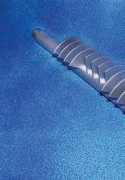
One challenging machine part was a cylindrical component used to separate small plastic parts after ejection from an automated molding machine. The 9 “-long, 303 stainless steel part has a dozen 0.6 “-tall × 0.060 “-thick radial fins that extend about a quarter of the way around the circumference of its 5⁄8 “-dia. shaft. In use, a computerized control rotates the shaft back and forth to selectively stop and release parts as they move beneath it.
Courtesy of OMW
When OMW machined this 9 “-long component for an automated manufacturing system from 303 stainless steel, the shop overcame challenges that included finding a way to quiet a dozen 0.060 “-thick fins that “rang like a bell” during a milling process.
OMW worked with a customer-provided SolidWorks model and programmed the part in SurfCAM. The first operations, performed in an Okuma turning center, involved turning a 2 “-dia. bar to the final OD of the fins and then stepping down to 5⁄8 ” for 3 ” at one end of the shaft. After flipping the bar in the lathe chuck, OMW turned the other end to 5⁄8 ” in diameter for 1.5 ” and then to a 3⁄8 “-dia. bearing surface for the shaft’s final 0.5 “.
Next, the bar was fixtured vertically in a Hwacheon Sirius-U vertical machining center with the 5⁄8 ” end up. That end was drilled with a center hole and milled for a length of 1 ” into a round-sided triangular shape.
OMW then returned the bar to the lathe to cut the 12 0.3 “-wide × 0.6 “-deep grooves to produce the fins. For support, the lathe’s tailstock was put in the center hole drilled earlier because “The grooving tool puts a lot of force on the part,” Osborn said. A Kennametal 0.120 “-wide grooving tool with an 0.008 ” radius cut the grooves at 838 rpm and a 0.0025-ipr feed rate, making three roughing and two finishing passes with flood coolant. The tool also created a 0.312 ” radius between each fin and the bottom of the groove and put 0.10 “-long, 45° chamfers on the top edges of the fins.
Then it was necessary to cut excess flute material from about three-quarters of the part diameter. To hold the bar horizontally on the VMC, OMW fabricated a square fixture plate with a central hole that matched the triangular shape at the part’s one end. The other end of the shaft went into a fixture that allowed it to rotate. The fixtures were clamped in vises on the VMC’s table, and OMW was able to flip the part in the vises and index it at 90° intervals. The shop probably could have accomplished similar results with an indexing table, Osborn said, but preferred to combine the accuracy of indexing via the square plate with the control of CAM software.
Cutting the excess flute material from the shaft, however, was “a tricky thing,” Osborn said. The fins were “too thin, only 0.060 ” wide. When you cut them away, they rang like a bell. That created chatter and terrible surface finish.” In addition, when the fins began to vibrate, the endmill often would catch on a fin and bend it. Osborn called the initial fin-cutting efforts “a disaster.”
The shop’s creative but simple cure for the ringing fins was aluminum spacers, about 0.3 ” wide × 0.75 ” tall × 0.5 ” long, pushed between the fins. The spacers were “kind of jammed in there and they wanted to fall out,” Osborn said, so they were attached one to another with a thin band of aluminum. “They stuck up about 1⁄8 “, but that didn’t matter because we weren’t machining exactly where they were. They were there to keep the fins from vibrating, to make the machining possible.”
The fix worked; a 4-flute, 3⁄8 “-dia., coated, solid-carbide bull nose endmill with a 0.0156 ” corner radius removed the excess fin material at 4,000 rpm and 20 ipm.
In addition to removing about three-quarters of each fin from around the shaft, Osborn said: “We had to go back and machine the last part of each fin away, perfectly matching the contour of the bar. It almost had to look like the fins were welded onto the bar. All we were allowed to leave was the bar’s round shape.”
Osborn said the indexing fixture developed in-house enabled the part to be indexed accurately, and, with the CAM software, “We did 3-D machining, planar passes, just to clean up the last bit of the fins. One of the nice things about 3-D machining” is that it enables a user to “save setups and basically simulate other types of machining.”
Except for the 3⁄8 “-dia. bearing surface and the triangular section on the ends, OMW bead-blasted the part after machining to finish it. CTE
For more information about OMW Corp., call (415)382-1669 or visit www.omw corp.com.
About the Author: Bill Kennedy, based in Latrobe, Pa., is contributing editor for Cutting Tool Engineering. He has an extensive background as a technical writer. Contact him at (724) 537-6182 or by e-mail at billk@jwr.com.
Glossary terms in this article
Related




Subscribers can use MFGAxis notes, saves and discussion tools with their innoNET account.


