P/M powers auto parts
Machining P/M steels for powertrain parts is tough, but answers abound.
Machining P/M steels for powertrain parts is tough, but answers abound.
Always on the hunt for lower weight, improved engine efficiency, lower costs and reduced noise and vibration, automakers are turning more frequently to powder metallurgy steel components for a variety of powertrain applications.
According to data from the Metal Powder Industries Federation, Princeton, N.J., use of P/M auto parts almost tripled over 3 decades, from about 35 lbs. in each vehicle in 1975 to nearly 100 lbs. per vehicle in 2005.
More recently, the sheer weight of P/M components used in each car and truck has leveled off, but the parts are making their way into a wider variety of powertrain applications, said Jim Dale, vice president, member and industry relations for MPIF. “For example, automakers have gone from four- to six-speed transmissions. That’s been a very positive development for the P/M industry, because more speeds mean more gears and other components, and those components need to fit into the same space. That means more smaller parts, and P/M is a good process for that.” Automotive designers are also learning to use the capabilities of P/M processing to consolidate several components into a single part, Dale said.
Historically, applications for P/M parts in powertrain applications include connecting rods, valve seats and many transmission gear and sprocket-type components. But newer applications are opening up throughout engines and transmissions.
For example, engines with variable valve timing use multiple parts to control the VVT system, which can save fuel, improve power and reduce emissions over a range of engine speeds. Most current VVT systems contain a P/M vane rotor, sprocket and thrust plate. Dale said each of the parts weighs about a pound and offers automakers substantial cost savings over wrought steel components. P/M component manufacturers currently supply an estimated 40 million P/M steel parts for VVT systems annually in North America, and the total is expected to grow to 70 million parts per year by 2015, according to MPIF.
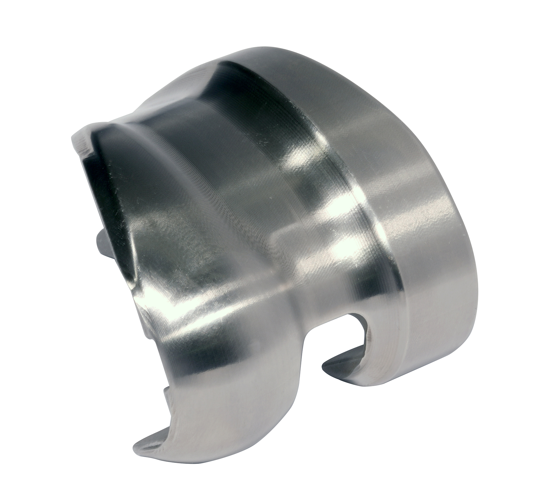
Courtesy of MPIF
P/M vane rotor, sprocket and thrust plate parts for variable valve timing systems weigh about a pound each and offer substantial cost savings over wrought steel components.
Dale said the VVT application is typical of how P/M can allow automakers to improve powertrain efficiency while reducing or holding the line on costs. “It comes down to more bang for the buck,” he said. “Use of P/M components can give engine and transmission designers some advantage for a comparable price, whether it’s lighter weight, improved performance or unique wear and design characteristics.”
According to Dale, P/M processing enables the creation of application-specific materials and supports the desire of automakers to reduce part counts. “One of the unique things about P/M is that chemistries are infinitely variable,” he said. “Compositions can be modified to optimize the material for a given application. So there are many different alloys being used for ferrous P/M powertrain components.”
Most P/M powertrain components are pressed and sintered. The powder material is first pressed to near-net shape, then heated to melt and consolidate the individual powder grains into a solid component. New processing methods are improving properties of P/M components dramatically. “We are now achieving tensile strengths in the hundreds of thousands of psi, comparable to forged or cast parts, and secondary processing can further improve properties and enable use of P/M parts in a wider variety of applications,” Dale said.
Porosity Puzzle
Regardless of how they are produced, most P/M components contain some porosity, which complicates machining, according to Don Graham, manager of turning products and educational services, Seco Tools Inc., Warren, Mich.
“Porosity means that, during machining of these parts, the cutting edge is doing interrupted cutting on a microscale,” Graham explained. “The tool will be cutting solid material, then a small part of the edge will hit a pore. At that point, the stress on that portion of the cutting edge goes to zero. Then, more solid material impacts that portion of the cutting edge, eventually leading to fatigue crack initiation and chipping along the cutting edge.”
According to Doug Evans, grade development specialist for Sandvik Coromant Co., Fair Lawn, N.J., porosity in P/M components puts added stress on tools. “The pores have relatively low conductivity, so heat will not be transported away from the cutting zone in an effective way,” he said. “This results in excessive heat-related wear on the insert.”
P/M components tend to be abrasive due to the materials’ microstructure, which consists of hard particles in a relatively soft matrix material. “The bulk hardness of an automotive component might be 30 HRC, but if you measure microhardness it could be 50 HRC,” Graham said. “That’s because when you check bulk hardness you are taking into account the porosity. The structure collapses a bit around the indenter because of the porosity, so you get an artificially low hardness reading.”
Evans said another key indicator is the difference in micro- and macro-hardness. “It is important to know the particle hardness as well as the apparent hardness or bulk hardness of the material when selecting the correct grades and cutting parameters.”
Making the Grade
As MPIF’s Dale pointed out, P/M steel can come in compositions that would be impossible to produce using conventional forging or casting techniques. According to Dr. Gabriel Dontu, global superhard technical leader, Kennametal Inc., Latrobe, Pa., the ability of P/M producers to develop materials tailored to specific applications can cause headaches for cutting tool suppliers tasked with developing machining processes for P/M powertrain components.
“The P/M parts business is really competitive and really secretive,” he said. “That can make it challenging to develop the most efficient machining processes. We’re trying to convince material producers to share samples of new materials they develop so we can optimize cutting conditions. That way, when they sell the materials to their customers, there’s already an optimized machining solution.”
Depending on material hardness, the gap between apparent and microhardness, machining processes and other conditions, appropriate cutting tool materials for P/M materials range from carbide inserts and cermet to PCBN.
According to Graham, inserts with Seco Tool’s Duratomic CVD aluminum-oxide coating can work well for P/M components. The Duratomic technology promotes growth of coating crystals in certain crystallographic directions to improve coating properties.
Evans said relatively soft P/M materials can be effectively machined using carbide or cermet tools. “When machining soft P/M parts with particle hardness and apparent hardness close to the same, carbide inserts such as Coromant 3215 and cermets such as CT5015 with sharp edge geometries can work well,” he said. “But the bigger the gap between apparent and particle hardness, the more demanding the machining. Those applications would benefit from use of CBN tools.”
Focus on Superhards
For harder P/M materials and those with wider gaps between apparent and particle hardness, the cutting tool manufacturers interviewed for this article agreed that PCBN tools are the way to go. Seco, for example, recommends its PCBN 200 grade, which gains improved toughness from its tungsten carbide/cobalt-based binder rather than the typical ceramic binder.
Dontu said highly abrasive materials, including P/M steels, require use of the hardest tool material that’s suitable for efficiently machining ferrous workpieces. “We use PCBN. Our high-content grades contain 85 to 93 percent CBN and have extremely high abrasion resistance.”
According to Dontu, Kenna-metal has developed tools with three levels of CBN content and different binders to address the problem of chemical reaction with the work material at high machining temperatures. “For higher-CBN grades, you need a binder that can handle a lot of heat, so the major component is aluminum oxide,” he explained. “The binders in low-content CBNs generally use TiC, TiN and TiCN. The ratio between those can be changed to give more impact resistance or chemical stability.”
Dontu said there is also a new generation of high-content PCBN tools that use intermetallic binders. “These materials absorb energy, so the tools are extremely tough—probably 50 percent higher in terms of impact strength compared with ones having an aluminum-oxide binder. So they’re good for milling or interrupted turning, but they are less heat resistant than aluminum oxide-based grades.”
Coatings are also crucial to maximize PCBN tool life when machining P/M materials. “It’s counterintuitive, because CBN is the second-hardest material known to man,” Dontu said. “But coatings change chemical behavior. In certain continuous cutting applications, we have seen tool life increases of 200 percent in the same material coated versus noncoated.” Kennametal’s PCBN-tool coating is a complex PVD TiAlN.
Sandvik is launching a new coated PCBN grade aimed specifically at P/M machining and hard turning applications. TiN-coated CB7525 is a high-content PCBN grade featuring six tips.
Positive and Negative
Review the print ads from this magazine to continue
This quick advertiser review unlocks the rest of the article and keeps the full-screen reader focused on the ads instead of the page chrome.


MFGAxis Discussion