



The Modern Art of Milling
Tips and techniques that can turn a standard milling job into a work of art.
Tips and techniques that can turn a standard milling job into a work of art.
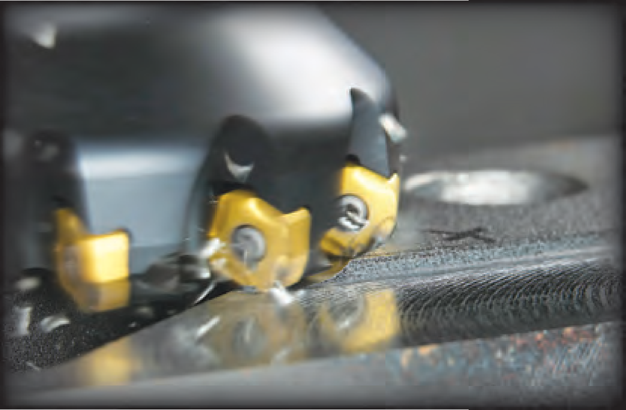
Recent developments in milling have the potential to save manufacturers substantial time and money by increasing throughput. From selecting the right milling cutter for the job to using a roll-in approach to facemilling and employing milling tools for holemaking when appropriate, manufacturers can improve milling productivity without investing a dime in new equipment.
Courtesy of All images: Sandvik Coromant Selecting the Right Tool
When choosing which milling cutter to apply, a host of factors must be considered, from the geometry and size of the part being produced to the workpiece material being machined.
When walking through a manufacturing facility, it is common to see a 90° mill for machining square shoulders being used for facemilling. In some instances, this is justified. If milling irregular shapes or castings with surfaces that cause the DOC to vary, this tool may be the best choice. In other cases, a standard 45° facemill can provide a significant benefit.
Because of chip thinning, where chip thickness is less than a cutter’s feed rate and occurs axially when a milling tool’s entry angle is less than 90°, entry angle has a substantial impact on the appropriate feed per tooth for a milling cutter. A facemill with a 45° entry angle causes chips to become thinner as they travel across the workpiece. The chip thickness is lower than the feed per tooth as the entry angle decreases. This, in turn, allows the feed rate to be increased by a factor of up to 1.4. Applying a mill with a 90° entry angle in this situation, however, reduces productivity up to 40 percent, due to not obtaining the axial chip thinning effect provided by a 45° entry angle tool.
End users often overlook cutter size—another important aspect of milling tool selection. Many shops facemilling large parts, such as engine blocks or airplane frame components, use relatively small-diameter tools. This leaves significant productivity savings on the table. Ideally, 70 percent of the cutter should be engaged. For example, a 2 ” facemill will only have a 1.4 ” engagement and offer low productivity when cutting multiple sides of a large part. A bigger tool will save significant time.
Facemill Optimization
Another way to improve milling operations is through facemill optimization. When programming a facemilling operation, end users must first consider how the tool enters the cut. Typically, this is done by simply coming straight into the workpiece (Figure 1). Such a method is usually accompanied by a banging sound that results from the tool producing a thick chip when the insert exits the cut. The insert pounds against the material, introducing vibration and producing tensile stresses that reduce tool life.
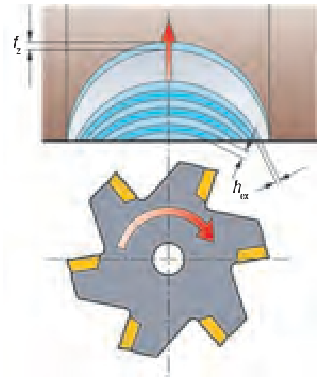
Figure 1. When facemilling, entering a cut straight on introduces vibration and produces tensile stresses that reduce tool life.
A better approach is a roll-in technique, where the mill rolls into the cut without reducing feed rates and cutting speeds (Figure 2). This involves rolling the cutter in a clockwise motion, ensuring that climb cutting takes place. This produces chips that start thick and end thin, minimizing vibration, reducing strain on the tool and increasing the amount of heat entering the chips. Tool life can double or triple by changing the way the tool enters each cut. The programmed radius of the toolpath to implement this technique is to use half the diameter of the tool and add the distance of the offset from the cutter to the workpiece.
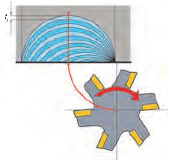
Figure 2. By rolling into a cut, a thick-to-thin chip is produced, reducing the strain on the tool and transferring a greater amount of heat into the chips.
While the roll-in technique refers to a tool entering a workpiece, the same general principle applies to staying in the cut whenever possible. Typically, a large facemilling application is programmed so the tool cuts along the full length of the part, steps over and completes the next cut in the opposite direction. It is usually better to integrate a spiral morph, or box method, rolling around the part’s corners to maintain constant radial engagement, eliminating the step-over. (Figure 3).
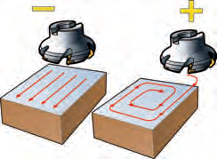
Figure 3. A spiral morph toolpath eliminates vibration and boosts tool life.
Macinists are familiar with the vibration-related noise that occurs when a tool enters a workpiece or makes a sharp, 90° turn while the tool is engaged. Rolling around corners eliminates this noise and extends tool life. Generally, the corner radius of the workpiece should be 75 to 100 percent of the tool diameter. This will reduce the cutter’s arc of engagement, reducing vibration and allowing higher feed rates.
Tool life can also be improved by not facemilling over holes or interruptions in the workpiece when possible. If a facemill is run across the middle of a hole on a component, the tool is climb milling on one side and conventional milling on the other, which beats up inserts. This can be avoided by programming toolpaths to go around holes and pockets.
Holemaking with Milling Tools
A growing number of manufacturers are helical, or circular, interpolating holes in parts using milling tools. Such approaches will never match the speed of drilling a hole, but can be advantageous for numerous applications.
When drilling irregular surfaces, it may be difficult to engage the centerline of the drill, causing the tool to walk across the part surface. Drills also require about 10 hp for each inch of diameter, meaning drilling may be less than optimal on low-horsepower machines. Additionally, some parts require a large number of different-size holes. If tool magazine capacity is limited, using a mill to create the holes can avoid machine downtime to load tools.
Tool size becomes especially important when using a milling tool for holemaking. If the diameter of the tool is too small for the diameter of the hole, the process can create a core of material at the hole’s center (Figure 4). When this core falls, it will damage the part or tool. A milling tool that is too large will damage itself and the workpiece, as the milling cutters are not center cutting and crash at the bottom of the tool (Figure 5).
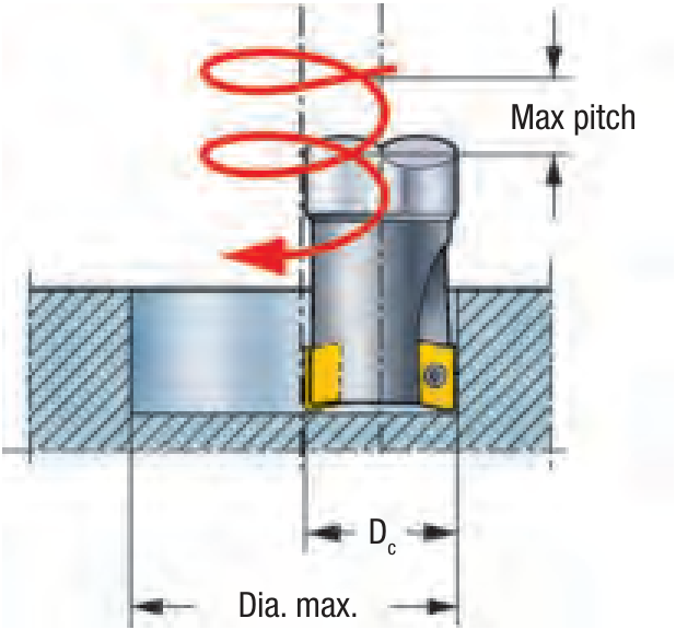
Figure 4. When using a mill for holemaking, employing too small of a mill results in a core at the hole’s center, which can damage the tool and part.
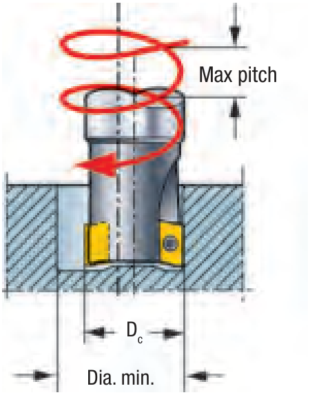
Figure 5. Likewise, also avoid using too large a tool because milling cutters are not center cutting and crash at the bottom of the tool.
Also, when holemaking with a milling cutter, the tool should be programmed from the tool centerline. When helical interpolating with an indexable-insert mill, the outside insert experiences a much higher feed rate than the tool centerline. Programmers often ignore this fact and accidentally apply feed rates that are too high for the tool to effectively handle.
By selecting the appropriate milling tool, having the tool engage the workpiece material to minimize vibration and tensile stresses and knowing when milling a hole is more effective than drilling one, manufacturers can efficiently and profitably turn blocks of metal into parts that might be suitable for exhibit at the Museum of Modern Art! CTE
 About the Author: William Durow is industry and applications engineer, milling products, for Sandvik Coromant Co., Fair Lawn, N.J. He has a degree in manufacturing engineering and over 20 years of manufacturing experience. Durow has worked for Sandvik Coromant for the past 13 years. Contact him at william.durow@sandvik.com.
Glossary terms in this article
Related




Subscribers can use MFGAxis notes, saves and discussion tools with their innoNET account.


