



Quantifying machine error motions
Quantifying machine tool error motions in this month's Machine Technology column by Dr. Scott Smith of the University of North Carolina at Charlotte.
Several factors influence part accuracy, including machine tool accuracy, cutting forces, dynamic motion loads and thermal conditions. Regarding machine tool accuracy, many of the efforts to measure and correct for machine positioning errors derive from error compensation of coordinate measuring machines. Purely kinematic errors arise because of errors in the creation or assembly of machine components. However, the errors imparted by the machine to the workpiece depend on the relative motions of those machine components.
Such errors are measured by “master part tracing.” In this concept, the cutting tool is replaced by a gage, and the workpiece is replaced by a master part, which has substantially tighter tolerances than the machine is capable of producing. The gage is then moved along the surfaces of the master part, following the toolpaths as if the part is being machined. Any deviation in the “0” reading of the gage indicates an error the machine motion would produce.
The master part is often conceptually comprised of straight edges and laser beams, and the machine motion errors are measured throughout the machine’s work space. It is possible to measure the vector error components (X, Y and Z) for a large number of points throughout the work space and store them in a lookup table, which might have hundreds of thousands of entries, for correction. Therefore, it is often more convenient to develop a mathematical model of the machine that uses functional errors of machine components and allows the error component to be computed.
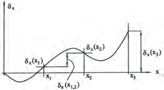
Chart courtesy of “Manufacturing Processes and Equipment,” by George Tlusty, Prentice Hall
Figure 1. Idealized linear positioning error in the direction of X-axis motion. The error is a function of axis position.
Even though the model ignores the time-varying thermal state of the machine and workpiece and the dynamic motion and cutting force loads on the machine, creating the error map can be complicated. The error map for a 3-axis machine tool, for example, has 21 functional error terms. A specialized notation has been developed to help measure and correct these errors.
To start, there are three linear positioning errors, one for each axis. In a machine with ballscrew drives, the ballscrews are not perfectly fabricated. As the screw rotates and the nut slides, the carriage moves a little more or a little less than planned. These linear positioning errors are denoted δx(X), δy(Y) and δz(Z), where the letter in the parenthesis indicates which axis is moving, the subscript indicates in which direction the error is measured and the symbol δ indicates a linear error, as opposed to rotational one. In addition, guide ways are not perfectly straight or attached to the machine frame. For any axis motion, there are six errors perpendicular to that motion. They are denoted δy(X), δz(X), δx(Y), δz(Y), δx(Z) and δy(Z). That makes nine error terms so far.
View print ads from this spread
Review the ads on this magazine spread to continue reading. Each ad takes two seconds; a two-page ad counts once.
Advertisers on this magazine spread
Print placements on this magazine spread
Schutteusa
Another class of errors is rotational. indicates the machine moved too little. to account for the error.
Because guide ways are not flat, as For a given machine position, the value Economic feasibility determines how each axis moves, the carriage may tip of each error function at that position can accurately a machine is built. To achieve forward or backward in the direction be mathematically combined to give the the required part accuracy, remaining.
Another class of errors is rotational. indicates the machine moved too little. to account for the error. Because guide ways are not flat, as For a given machine position, the value Economic feasibility determines how each axis moves, the carriage may tip of each error function at that position can accurately a machine is built. To achieve forward or backward in the direction be mathematically combined to give the the required part accuracy, remaining of travel (pitch), turn right or left from geometric error of the machine. The com- geometric errors are corrected through the direction of travel (yaw) or rotate manded machine position can be altered software. CTE clockwise or counterclockwise around the axis of travel (roll). The roll errors are denoted εx(X), εy(Y) and εz(Z), where ε indicates an angular error, the subscript
Visit Schutteusa View this placement in the issue recordPrint ads from this magazine
Because guide ways are not flat, as For a given machine position, the value Economic feasibility determines how each axis moves, the carriage may tip of each error function at that position can accurately a machine is built. To achieve forward or backward in the direction be mathematically combined to give the the required part accuracy, remaining.
Another class of errors is rotational. indicates the machine moved too little. to account for the error. Because guide ways are not flat, as For a given machine position, the value Economic feasibility determines how each axis moves, the carriage may tip of each error function at that position can accurately a machine is built. To achieve forward or backward in the direction be mathematically combined to give the the required part accuracy, remaining of travel (pitch), turn right or left from geometric error of the machine. The com- geometric errors are corrected through the direction of travel (yaw) or rotate manded machine position can be altered software. CTE clockwise or counterclockwise around the axis of travel (roll). The roll errors are denoted εx(X), εy(Y) and εz(Z), where ε indicates an angular error, the subscript
Continue reading
December 2011
Another class of errors is rotational. Because guide ways are not flat, as each axis moves, the carriage may tip forward or backward in the direction of travel (pitch), turn right or left from the direction of travel (yaw) or rotate clockwise or counterclockwise around the axis of travel (roll). The roll errors are denoted εx(X), εy(Y) and εz(Z), where ε indicates an angular error, the subscript indicates the axis around which the angular error is measured and the letter in parenthesis indicates which axis is moving. Similarly, the pitch and yaw error terms are denoted εy(X), εz(X), εx(Y), εz(Y), εx(Z) and εy(Z), for a total of 18 error terms so far.
The last category of error terms is relative squareness of the axes. As a builder assembles a machine, it is not possible to make the axis motions exactly perpendicular to each other. As a result, planned motion around a square, for example, is motion around a parallelogram instead. There are three squareness errors: αxy, αxz and αyz. The symbol α indicates a squareness error, and the two subscripts indicate the two axes between which the squareness is to be measured. With the addition of these three, the total equals 21 error terms.
Each error term is not a number, but rather a function of the position of the moving axis (Figure 1). In this simplified case, the gage was set to zero when the X-axis position was zero. As the X-axis moved, the X-axis position was measured and plotted. A positive error indicates the axis moved too far, and a negative error indicates the machine moved too little.
For a given machine position, the value of each error function at that position can be mathematically combined to give the geometric error of the machine. The commanded machine position can be altered to account for the error.
 Economic feasibility determines how accurately a machine is built. To achieve the required part accuracy, remaining geometric errors are corrected through software. CTE
About the Author: Dr. Scott Smith is a professor and chair of the Department of Mechanical Engineering at the William States Lee College of Engineering, University of North Carolina at Charlotte, specializing in machine tool structural dynamics. Contact him via e-mail at kssmith@uncc.edu.
Glossary terms in this article
Related




Subscribers can use MFGAxis notes, saves and discussion tools with their innoNET account.


