

Extend tool life with dynamic toolpaths
Get With The Program, a regular column in Cutting Tool Engineering magazine, covers how to extend tool life with dynamic toolpaths.
There are three requirements for achieving long tool life: the cutting tool must be applied correctly, it must be as rigid as possible in its holder, and the CAM programming software must effectively control the tool’s path, speed and entry/exit strategy. The tool’s trajectory is a key element in maximizing its performance. In addition to extending tool life, new CAM software developments enhance machining speed and efficiency.
Courtesy of CNC Software
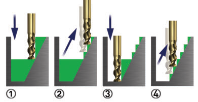
An OptiRough toolpath can cut material in two directions: step-down (-Z) and step-up (+Z). Large, aggressive down-cuts are followed by fast, smaller up-cuts. This efficient cutting strategy removes the maximum amount of material with the minimum number of step-downs, significantly reducing cycle times.
Courtesy of Iscar Metals
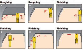
An Iscar CUTGRIP tool cuts with all three sides of the insert: the floor and the walls on both sides. This enables the cutting tool to combine roughing and finishing.
Machine tools have traditionally been driven with algorithms developed years ago, such as a parallel-type machining motion or, perhaps, a collapse/expansion method of calculating the toolpath. While those traditional methods are clearly outmoded, some shops still use them because they understand and trust them. These shops don’t tend to experiment with newer types of motion, such as dynamic toolpaths. As a result, they are missing out on an opportunity to improve productivity.
For example, Mastercam software provides OptiRough, a new technique for quickly removing large amounts of material using a dynamic milling motion. Dynamic milling constantly adjusts the toolpath to ensure the most efficient cut possible and allows the use of the entire tool-flute length, often minimizing the amount of multiple-depth cuts.
Instead, large, aggressive down-cuts are followed by fast, smaller up-cuts because the OptiRough toolpath recognizes the steps created from the previous down-cut and then removes the steps to more efficiently expose the part’s near-net shape.
Review the print ads from this magazine to continue
This quick advertiser review unlocks the rest of the article and keeps the full-screen reader focused on the ads instead of the page chrome.
Advertisers included in this article experience
Print placements connected to this article
Mmus
Best in Class, Technology-Driven Solutions.
A LEADER IN MANUFACTURING PROCESS TECHNOLOGIES The Mitsubishi Materials name is tantamount to quality, technological leadership, and diversity in product offerings. We partner with industries such as medical, automotive, oil & gas, aerospace, and die & mold. Our three diamond logo represents what demanding customers can expect.
Best in Class, Technology-Driven Solutions. A LEADER IN MANUFACTURING PROCESS TECHNOLOGIES The Mitsubishi Materials name is tantamount to quality, technological leadership, and diversity in product offerings. We partner with industries such as medical, automotive, oil & gas, aerospace, and die & mold. Our three diamond logo represents what demanding customers can expect Visit us at IMTS booth from our materials, products, services, and our outstanding employees. W1426 or, for more Mitsubishi Materials manufacturing plants are world-class operations, information, contact Mitsubishi Materials
Visit Mmus View this placement in the issue recordPrint ads from this magazine
A LEADER IN MANUFACTURING PROCESS TECHNOLOGIES The Mitsubishi Materials name is tantamount to quality, technological leadership, and diversity in product offerings. We partner with industries such as medical, automotive, oil & gas, aerospace, and die & mold. Our three diamond logo represents what demanding customers can expect.
Best in Class, Technology-Driven Solutions. A LEADER IN MANUFACTURING PROCESS TECHNOLOGIES The Mitsubishi Materials name is tantamount to quality, technological leadership, and diversity in product offerings. We partner with industries such as medical, automotive, oil & gas, aerospace, and die & mold. Our three diamond logo represents what demanding customers can expect Visit us at IMTS booth from our materials, products, services, and our outstanding employees. W1426 or, for more Mitsubishi Materials manufacturing plants are world-class operations, information, contact Mitsubishi Materials
Continue reading
September 2012
Traditional methods require more tool travel because the user must program each step-down as a full width instead of simply removing the steps. Optirough optimizes cutter motion because it recognizes the remaining stock and removes material in two directions: step-down (-Z-axis) and step-up (+Z-axis). This bidirectional cutting strategy removes the maximum amount of material with the minimum number of full stock-width steps to achieve the same results, significantly reducing cycle times.
Likewise, new CAM software finishing techniques intelligently blend two efficient cutting motions in a single toolpath. The resulting toolpath evaluates the model shape and smoothly switches between constant Z-axis cutting and constant scallop cutting. The result is a fine surface finish with minimal tool wear.
Another technique uses an intelligent, efficient, high-speed contouring strategy to remove material along walls. It supports multiple passes and can include finishing passes. It’s almost as though the newer CAM software intelligence “understands” where the stock is and the best way to remove it so as not to abuse the cutting tools, which extends tool life while maximizing machining efficiency.
In addition to milling, new CAM-generated toolpath options are available for turning. For example, these toolpaths are helping users maximize turning and grooving cutting tools with CUTGRIP plunge-groove technology from Iscar Metals Inc., Arlington, Texas. (The grooving tools are specifically designed for groove turning on a lathe.)
In addition to the path a cutting tool takes once engaged with the workpiece, how a tool enters and exits material has a profound effect on its life. Old-style techniques often direct a tool straight into the material. For example, when a facemill is directed straight into a square block, the entry shocks the tool, causing micro fissures and cracks that can lead to heat breaking down the tool coating and causing tool failure.
The best practice is to enter the workpiece with an arc motion. Assuming a right-hand cut or spiral, the tool should follow a right-hand arc as it enters the workpiece. It’s a gentler, more gradual way of initiating the cut.
All CAM software developers are developing toolpaths that increase speed and efficiency and extend tool life. The users are the beneficiaries of these new technologies, but only if they are correctly applied.
It is human nature to stick with what works, even when there is something better. It might be a cutting tool, a toolholder or a “secret” in the CAM software package that has yet to be unearthed. Open the “box,” play with the new toys and change your shop for the better! CTE

About the Author: Director of International Sales and Strategic Partnerships Steve Bertrand is based at CNC Software Inc.’s headquarters in Tolland, Conn. For more information about the company’s Mastercam CAM software, call (800) 228-2877 or visit www.mastercam.com.
Glossary terms in this article
Related



Subscribers can use MFGAxis notes, saves and discussion tools with their innoNET account.


