

Milling heads don’t get the shaft
Overcome excessive tool wear and poor surface finishes when machining flats on a steel truck shaft. A milling tool that exerts all cutting forces downward and cuts freely.
END USER: Machine Tool & Gear Inc., (989) 743-3936, www.machinetoolgear.com.
CHALLENGE: Overcome excessive tool wear and poor surface finishes when machining flats on a steel truck shaft.
SOLUTION: A milling tool that exerts all cutting forces downward and cuts freely.
SOLUTION PROVIDER: Horn USA Inc., (888) 818-HORN, www.hornusa.com.
The last thing a tool distributor wants is for a customer to return an expensive product because it can’t produce acceptable parts. PF Markey Inc., headquartered in Saginaw, Mich., faced this possibility after the distributor sold two 90° milling heads that cost about $10,000 each to Machine Tool & Gear Inc., Owosso, Mich. The heads, which attach to the machine tool spindle and accept a cutting tool, were to machine shafts on a Mori Seiki NH 4000 horizontal machining center at the company’s plant in Corunna, Mich.
MT&G purchased the heads when a new truck shaft design included two flat areas 180° apart that must be machined at 90° from other operations, because adding a machine and fixtures to perform the additional process would have been cost-prohibitive, according to MT&G Manufacturing Engineer Jeff Ochodnicky. However, MT&G experienced excessive tool wear and poor surface finishes when cutting with the heads—even after experimenting with numerous machining parameters.
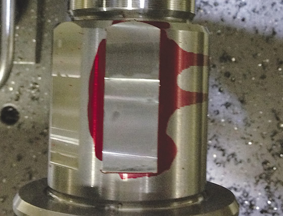
The Mini Mill tool (below) from Horn USA enables Machine Tool & Gear to achieve a 15 to 20 µin. Ra surface finish when milling flats in a steel truck shaft.
That’s when Brett Kischnick, applications engineer for toolmaker Horn USA Inc., Franklin, Tenn., got a call. “Phil Horn, at the distributor, said, ‘I don’t want them to return these heads’ and asked if I could do anything to help.” Kischnick replied, “Let me at it.”
The challenge was milling flats 1.500 ” (38.1mm) long and 0.060 ” (1.524mm) deep on a steel shaft with a cutting tool 0.854 ” (21.692mm) in diameter that hangs more than 10 ” (254mm) from the spindle and rotates at 90° to the spindle via gears. That arrangement created rigidity and chatter issues, Kischnick noted.
He added that the milling tool MT&G was applying is designed primarily for side milling slots and has a staggered flute arrangement that alternates between a helical twist on the flute that pulls, or lifts, a chip, and a helical twist that pushes a chip. “One flute was pushing down and the next one was pulling up and causing vibration in an unstable setup with the 90° head,” Kischnick said, noting MT&G was using a straight-shank toolholder that went into a collet.
Review the print ads from this magazine to continue
This quick advertiser review unlocks the rest of the article and keeps the full-screen reader focused on the ads instead of the page chrome.
Advertisers included in this article experience
Print placements connected to this article
Iscar
Intelligently large diameter drilling with unique insert clamping
Iscar promotes self-centering large-diameter drilling with a clamping mechanism designed for accuracy and longer tool life.
Intelligently large diameter drilling with unique insert clamping Iscar promotes self-centering large-diameter drilling with a clamping mechanism designed for accuracy and longer tool life. Visit iscarmetals.com to learn more.
Visit Iscar View this placement in the issue recordPrint ads from this magazine
Iscar promotes self-centering large-diameter drilling with a clamping mechanism designed for accuracy and longer tool life.
Intelligently large diameter drilling with unique insert clamping Iscar promotes self-centering large-diameter drilling with a clamping mechanism designed for accuracy and longer tool life. Visit iscarmetals.com to learn more.
Continue reading
March 2015
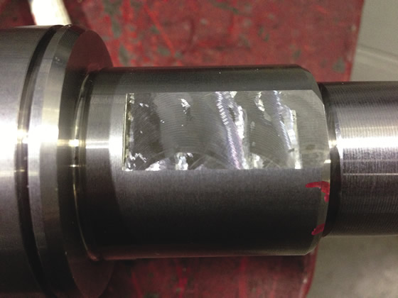
Machine Tool & Gear was imparting unacceptable surface finishes when milling flats.
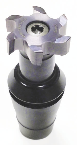
Kischnick proposed replacing the milling tool with Horn’s Mini Mill, which is designed for facemilling and has a positive axial helix on all flutes, so the cutting forces are in one direction—downward. To further enhance rigidity, the Mini Mill’s steel holder eliminates the collet. “It has the shape of an ER20 collet on the back end, and the front end is actually the endmill holder all in one piece,” he explained.
Achieving the specified surface finish of 30 µin. Ra without an additional operation between the roughing and finishing passes required minimizing cutting pressure by reducing the number of teeth in the cut from six to three and leaving only 0.002 ” (0.051mm) of material for the finishing pass. In addition, Kischnick employed a “trick” to relieve multidirectional tool pressure, which causes a tool to chatter and cut less freely. The trick is to move the tool “a few thousandths of an inch” from a flat’s sidewall during finishing.
“Any time you cut with the side and the bottom of a tool at the same time, you have opposing cutting forces against the tool: one at the bottom and one radially,” Kischnick said. “What I wanted was only to cut with the floor, or bottom, of the tool, and not have any of the sidewall hit the flutes, which makes the tool bounce.” That approach imparted a fine surface finish, he added.
After spending about 6 hours on the application, Kischnick noted the Mini Mill imparted a 15 to 20 µin. Ra surface finish. The final machining parameters are 715 sfm (217.932 m/min.) for roughing and finishing, a 0.058 ” (1.473mm) DOC for roughing and a 0.002 ” DOC for finishing, and a 0.004 ” (0.107mm) ipt for roughing and a 0.002 ” ipt for finishing. Because the previous tool could only achieve a surface finish of 80 to 100 µin. Ra, MG&T didn’t have any qualified speeds and feeds for producing the flats with that tool, he added.
“I was very impressed with Horn USA’s knowledge and how they took the time to help solve the problem,” MT&G’s Ochodnicky said. “As a result, we saved the expense of buying another machine tool and kept additional labor costs out of our process.”
Glossary terms in this article
Related




Subscribers can use MFGAxis notes, saves and discussion tools with their innoNET account.


