

Milling with constant force
There are many reasons for cutting force to vary, even during stable milling. These include tool teeth entering and exiting the cut, instantaneous changes in chip thickness, and tooth orientation changing as the tool rotates. However, it is possible to arrange the cutting conditions in a simple way and keep the cutting force constant.
There are many reasons for cutting force to vary, even during stable milling. These include tool teeth entering and exiting the cut, instantaneous changes in chip thickness, and tooth orientation changing as the tool rotates. However, it is possible to arrange the cutting conditions in a simple way and keep the cutting force constant.
Figure 1 shows a single tooth removing a chip as it moves along a workpiece, similar to a skiving operation. The force has to be sufficient to cause shearing in the cutting zone and ploughing (pushing some material out of the way in the cutting zone) and to overcome friction as the chip slides along the tool rake face. Most of the work winds up as heat in the chips, tool and workpiece.

All images courtesy S. Smith
Figure 1. Cutting forces for a single tooth removing a chip.
In Figure 1, the blue arrow (F) indicates the force of the chip on the tool. It has components in both the tangential direction (FT) and the perpendicular, normal direction (F). Many experiments have shown that the tangential component of the force is proportional to the chip thickness (h), the chip width (in the Z dimension) and a material property called specific power (Ks). The equation is FT= Ksbh.
If the workpiece is aluminum, Ks is about 850 N/mm2. If the chip width is 10mm (0.39″) and the chip thickness is 0.1mm (0.004″), the tangential component of the force would be 850 N. The normal component is proportional to the tangential component, and a typical ratio is about 0.3:1 (F = 0.3FT). For the conditions listed, F equals 255 N.
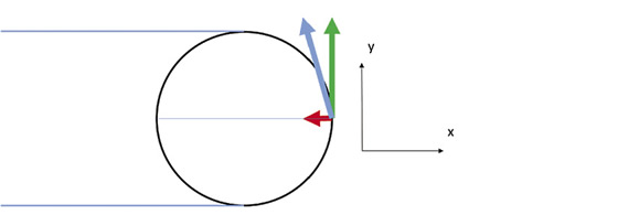
Figure 2. Forces on a two-toothed tool rotating clockwise and slotting in the X direction.
When milling, the same formulas apply, but the direction of the force and the chip thickness both change as the tool rotates. Figure 2 shows a two-toothed tool rotating clockwise, feeding to the right and creating a slot. As the tooth rotates through the cut, the chip thickness starts at 0 when the tooth is vertical, reaches its maximum when the tooth is in the position shown and thins until the tooth exits the cut at the bottom. The chip thickness is approximately h×sin(Φ), where Φ is the angular position of the tooth, measured from vertical.
It is easy to see that the force will not be constant for a two-toothed tool. It will start small, get large, then get small again, and the direction of the force will change as the tool rotates. The force will also vary for a three-toothed tool. However, if the tool has four teeth and is applied when slotting, something unusual happens—the forces on all the teeth sum to a constant.
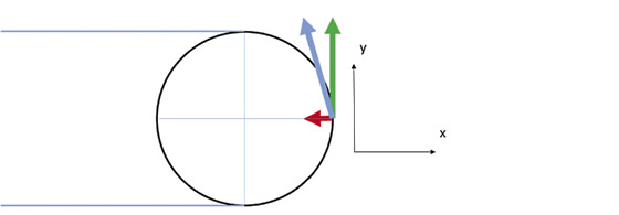
Figure 3. Forces on a four-toothed tool rotating clockwise and slotting in the X direction, with only one tooth engaged.
Review the print ads from this magazine to continue
This quick advertiser review unlocks the rest of the article and keeps the full-screen reader focused on the ads instead of the page chrome.
Advertisers included in this article experience
Print placements connected to this article
Rohm Products
staying sharp
shop technology Selecting the proper toolholder By Christopher Tate The foundation of robust and success- ful CNC milling and drilling processes consists of numerous elements, includ- ing high-quality machine tools, sturdy workholders and high-performance cut- ting tools. Toolholders are another of the basic elements. Thumb through trade publi-.
staying sharp shop technology Selecting the proper toolholder By Christopher Tate The foundation of robust and success- ful CNC milling and drilling processes consists of numerous elements, includ- ing high-quality machine tools, sturdy workholders and high-performance cut- ting tools.
Visit Rohm Products View this placement in the issue recordPrint ads from this magazine
shop technology Selecting the proper toolholder By Christopher Tate The foundation of robust and success- ful CNC milling and drilling processes consists of numerous elements, includ- ing high-quality machine tools, sturdy workholders and high-performance cut- ting tools. Toolholders are another of the basic elements. Thumb through trade publi-.
staying sharp shop technology Selecting the proper toolholder By Christopher Tate The foundation of robust and success- ful CNC milling and drilling processes consists of numerous elements, includ- ing high-quality machine tools, sturdy workholders and high-performance cut- ting tools.
Continue reading
June 2014
Figure 3 shows a four-toothed tool making a slot. One tooth is in the 0° position (top), so the chip thickness is 0 and the forces on that tooth are 0. One tooth is in the 90° position (to the right), and forces are exerted, just like in Figure 2. The third tooth is in the 180° position, and the chip thickness is back to 0, so there is no force on that tooth either. The fourth tooth is out of the cut, so there is no force on that tooth. Only one tooth is cutting, and the total force in the Y direction is the tangential component of the force on that tooth.
The total force in the X direction is the normal component of the force on that tooth. Again, let’s say the workpiece is aluminum, the maximum chip thickness (feed per tooth) is 0.1mm, and the chip width is 10mm. For this position of the tool, the force in the Y direction is 850 N, and the force in the X direction is -255 N, just as it would have been for a two-toothed tool.
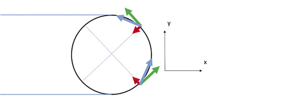
Figure 4. Forces on a four-toothed tool rotating clockwise and slotting in the X direction, with two teeth engaged.
Figure 4 shows the same tool rotated 45°. Now two teeth are cutting, one at the 45° position and one at the 135° position. The chip thicknesses at those two positions is smaller than in Figure 3, but they are equal to each other (sin 45° = sin 135°). The force lines point in different directions, and their sums give the total force. For the Y direction, the components of the normal forces (red) cancel, but the components of the tangential forces (green) add. So the total force in the Y direction is, using the same conditions, 850 N.
FY = Ksbh×sin(45°)cos(45°)+ Ksbh×sin(135°)cos(45°) = 850 N
This is the same as when one tooth is cutting. For the total force in the X direction, the components of the tangential forces cancel, but the components of the normal forces add:
FX = 0.3Ksbh×sin(45°)sin(45°)+ 0.3Ksbh×sin(135°)sin (45°) = 255 N
This is also the same as when one tooth is cutting. The totals come out the same for all other orientations.
Try it, or better yet, make a slot with a four-toothed tool and listen to how quiet it is. The helix does not matter if it is constant, because the calculation holds for each little slice of the tool along the tool axis. Constant force milling happens whenever there are an even number of teeth greater than two cutting a stable slot. CTE
About the Author: Dr. Scott Smith is a professor and chair of the Department of Mechanical Engineering at the William States Lee College of Engineering, University of North Carolina at Charlotte, specializing in machine tool structural dynamics. Contact him via e-mail at kssmith@uncc.edu.
Glossary terms in this article
Related




Subscribers can use MFGAxis notes, saves and discussion tools with their innoNET account.


