Mimicking machines with simulation
If you're new to 5-axis machining, simulation software can help you efficiently set up a post-processor and verify the strategies coming from the CAM system, according to this month's Get With the Program column.
Costly parts and complex machine tools require a G-code program to be verified prior to pressing a machine’s start button. If you are new to 5-axis machining, whether it’s with a milling or multitask machine, consider obtaining assistance from simulation software to efficiently set up a post-processor and verify the strategies coming directly from the CAM system. If you are already familiar with 5-axis machining, G-code simulation will help reduce noncutting time.
But how can you ensure 3-D simulation generates accurate results to entirely replace the prove-out process usually done on a real machine? The following information should strengthen your confidence.
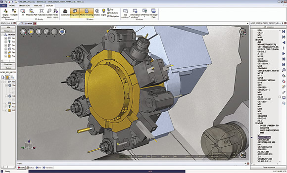
Courtesy of SPRING Technologies
When the space becomes tight, such as on a DMG / Mori Seiki mill/turn machine, simulation software provides critical tooling details.
When done directly on a real machine, the G-code validation process involves three basic steps.
1. Identify program errors. When loading a G-code program for the first time in a machine, the control might provide alarms linked to code integrity. Errors, such as unknown codes, inconsistent motions and out-of-range movements, are identified and require a user to go back and work on the CAM system or post-processor or edit the G code to make it work properly.
2. Check collisions. A dry-run test can consume tedious hours when done directly on the machine. It involves loading the tools in their stations, setting up the fixture and potentially mounting a soft foam-like material as a test workpiece. Some complex programs demand hours of verification with slow motions, but, if executed too quickly, this exercise can cause a dramatic crash. Therefore, it’s risky and potentially expensive. Common errors occur from incorrect program origins, a cutting motion in material with the spindle stopped, insufficient tool length or a rapid motion to reach a tool-change position that generates a tool move across a part and damages it.
3. Inspect the first piece. This part inspection, for example, determines incorrect tool compensations or missing operations.
Review the print ads from this magazine to continue
This quick advertiser review unlocks the rest of the article and keeps the full-screen reader focused on the ads instead of the page chrome.


MFGAxis Discussion