Isolating cutting operations: Turning Performance
The accurate positioning of the cutting tool with respect to the workpiece partly controls the accuracy of a machined part.
The accurate positioning of the cutting tool with respect to the workpiece partly controls the accuracy of a machined part. The tool may not be accurately positioned for a number of reasons, including programming errors, interpolation errors, kinematic errors of the machine tool components or workpiece, thermal deformations, and deflections caused by cutting forces and inertial or gravitational loads. Additionally, machine tools are often positioned near other machines and may be exposed to vibrations transmitted through the supporting floor.
Courtesy of S. Smith
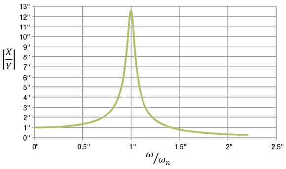
Figure 1. The magnitude of bed motion (X) compared to the magnitude of floor motion (Y) as a function of the floor motion frequency (ω) and the natural frequency of the system (ωn) for a scenario with low damping (c).
It is possible to design the machine tool bed and the mounting elements, which attach the machine to the floor, to passively isolate the machine. Passive isolation means the transmission of the floor motion to the cutting zone of the machine is naturally minimized without using power or a control system. Figure 2 illustrates a simplified model of the basic principle, in which the machine bed is modeled as a mass that can only move in the vertical direction. It is mounted to the floor through supports represented by a spring and a damper. The floor also moves only in the vertical direction.
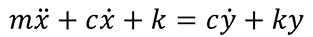
The bed motion is indicated by x, the floor motion by y, the bed mass by m, the damping (like a shock absorber) of the mounting element by c, and the stiffness (like a spring) of the mounting element by k. The equation that relates the motion of the bed to the floor is:

Mathematically, this is a linear, second-order, differential equation with constant coefficients. The x and y without dots indicate displacements of the coordinates, the two dots indicate acceleration and the single dots indicate velocities. This equation can be rearranged as:
The left-hand side of the equation looks like a single-degree-of-freedom system, and the right-hand side is the excitation caused by the motion of the base. As with other vibration problems, this equation has a solution that depends on the excitation frequency. That is, the size of the bed motion compared to the size of the floor motion depends on the motion frequency of the floor compared to the natural frequency of the system. The solution to that equation is shown in Figure 1.
Review the print ads from this magazine to continue
This quick advertiser review unlocks the rest of the article and keeps the full-screen reader focused on the ads instead of the page chrome.


MFGAxis Discussion