



Ask The Grinding Doc: Decrease diameter, increase speed
Dear Doc: I installed a variable-speed drive on a cylindrical grinder. The wheels start at 18" and stub-out at 15". Should I increase the rpm as the wheel diameter gets smaller? Read the full report for the Doc's reply.
Dear Doc: I installed a variable-speed drive on a cylindrical grinder. The wheels start at 18″ and stub-out at 15″. Should I increase the rpm as the wheel diameter gets smaller?
The Doc Replies: If you want more consistent grinding, maintain a constant surface speed. The basic equation is: new rpm = original rpm × original diameter ÷ current diameter. So, if you were happily running your new 18″ wheel at 1,800 rpm, once it gets down to 15″, run it at 2,160 rpm (1,800 × 18 ÷ 15). Be sure to stay within the maximum safe speed printed on the wheel
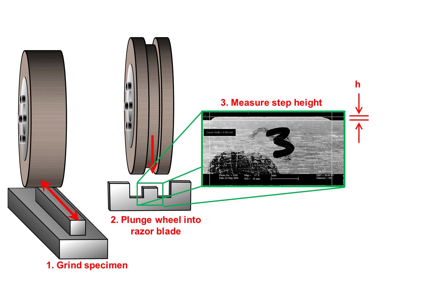
The steps to measure wheel wear with the “razor blade test.” Image courtesy of J. Badger.
That’ll help you maintain a fairly constant chip load during grinding. As the wheel diameter gets smaller, the grinding arc length gets smaller, meaning fewer grits are in the action. If you want to maintain exactly the same chip load, the equation is: new rpm = original rpm × (original diameter ÷ current diameter)1.5. So, if you were running your new 18″ wheel at 1,800 rpm, run it at 2,366 rpm [1,800 × (18 ÷ 15)1.5] once it gets down to 15″—again, within the safe speed.
If the CNC program inputs surface speed and not rpm, the equation is: new surface speed = original surface speed × √(original diameter ÷ current diameter). So, if you were running your new 18″ wheel at 8,500 sfm, once it gets down to 15″, run it at 9,311 sfm [8,500 × √(18 ÷ 15)].
The one thing you can’t correct for is that the smaller-diameter wheel now has a smaller circumference, meaning fewer abrasive grits are available to do the work. When a wheel goes from 18″ to 15″, you can expect 20 percent greater radial wheel wear (18 ÷ 15 = 1.2 = a 20 percent increase). Theoretically, you should have to dress 20 percent more often and expect 20 percent more radial form loss.
Dear Doc: In a previous column, you covered a “razor blade test” for measuring wheel wear. How does that work?
The Doc Replies: Let’s say a wheel is 2″ wide, and you grind a workpiece that’s 1″ wide. That leaves a step in the wheel. Mount a thin piece of material, such as a razor blade or piece of graphite, into a vise and gently plunge the wheel into it. That step is reproduced in the razor blade.
Then use a depth micrometer, an optical microscope or a scanning electron microscope to measure the height of the step. Plug that into the formula for G ratio to assess the relative wheel wear between different wheels, coolants and parameters: G ratio = (depth ground × length ground) ÷ (π × wheel diameter × step height). There are fancier ways to measure wheel wear using optics, lasers and acoustics, but this tried-and-true method is easy, reliable and accurate.
The razor blade test is more geared toward the lab than for production.
Glossary terms in this article
Related




Subscribers can use MFGAxis notes, saves and discussion tools with their innoNET account.


