Barber pole: General Industry Coverage
The Grinding Doc breaks down the causes and solutions for these workpiece spiral marks.
Dear Doc: We battle “barber pole” in cylindrical-traverse grinding. Where does it come from? And how can we get rid of it?
The Doc replies: Barber pole, also called pitch lines, screw lines, lead lines, traverse lines, thread lines and many other names, is caused by a Z-axis deviation in wheel shape (or even wheel sharpness) being imparted into the workpiece. As the wheel traverses the workpiece, this deviation repeats itself every pitch distance, which is calculated by: pitch (in inches or mm) = traverse velocity (in inches/minute or mm/minute) ÷ workpiece RPM.
This deviation doesn’t have to be large. In fact, often it’s so small that it can’t be measured. But it can be seen with the naked eye.
The two most common causes are a worn wheel and a misalignment between the wheel Z-axis and the workpiece Z-axis.
Let’s start with wheel wear. The figure shows different wheel-wear profiles. In most situations where the overlap ratio is greater than 2, the wheel rounds up, either in the middle or on one side. The end result is that the imperfect wheel imparts itself into the workpiece – and repeats itself every pitch distance.
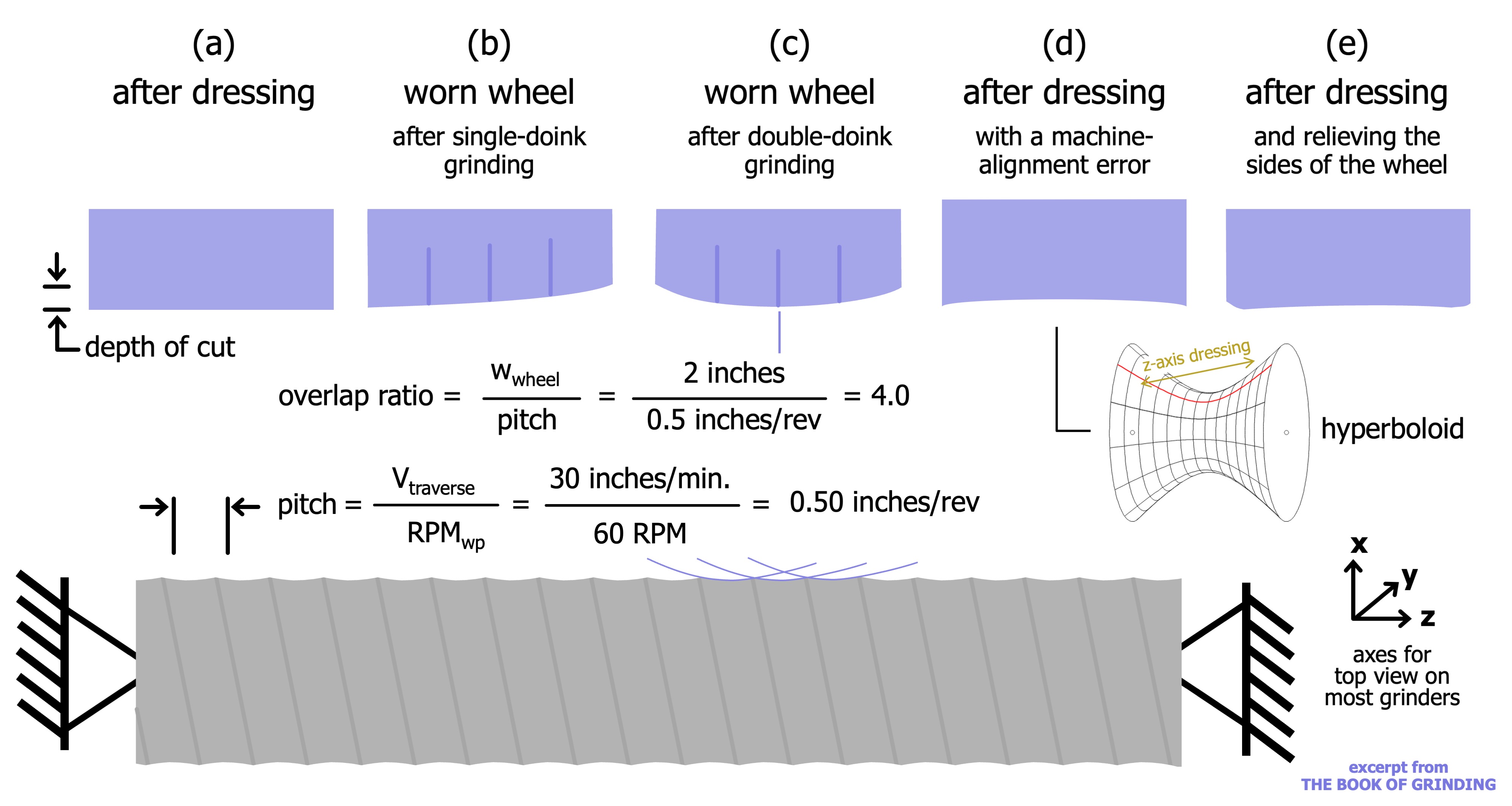
The solution? Dress, which turns your wheel back into a cylinder.
Review the print ads from this magazine to continue
This quick advertiser review unlocks the rest of the article and keeps the full-screen reader focused on the ads instead of the page chrome.


MFGAxis Discussion