Calculated forces when turning
Calculated forces when turning
The cutting force when turning is a resultant force that combines tangential, feed and radial force components. These force components can be measured with a three-component force dynamometer. Metalcutting professionals consider Kistler dynamometers the most accurate.
Using a new calculation for determining cutting force components and power when turning.
All images courtesy Kennametal
The cutting force when turning is a resultant force that combines tangential, feed and radial force components. These force components can be measured with a three-component force dynamometer. Metalcutting professionals consider Kistler dynamometers the most accurate.
Of the three cutting force components, the tangential force (FZ) is the greatest, the feed force (FY) is less in magnitude and the radial force (FX) is the least in magnitude. As a rule of thumb, the following relationships are used, but it is not a good practice because the results are not as accurate as they could be: FY = 0.50FZ and FX = 0.25FZ.

A Kennametal CNMG 120408 RN insert was applied for the roughing test.
On Oct. 25, 2012, Kennametal conducted lab tests at its facility in Fürth, Germany, turning 218-HB alloy steel AISI 4140 (DIN 1.7225 42CrMo4), with the following indexable inserts (ISO specification is in the metric system):
• CNMG 120408 RN for roughing, carbide grade is KCP10;
• CNMG 120408 MN for semifinishing, carbide grade is KCP10; and
• CNMG 120408 FP for finishing, carbide grade is KCP10.
A Boehringer VDF315C CNC lathe and a Kistler quartz-crystal, three-component toolholder dynamometer, type Z15814, were used for the lab tests. The lathe has 80kW (107 hp) of power, 1,400 Nm (1,032 ft.-lbs.) of torque and a VDI 60 turret. The cutting force components (FX, FY and FZ) were recorded (Charts 1, 2 and 3 for roughing below) and tabulated (Tables 1, 2 and 3 below).
The ratios of the feed force to tangential force and the radial force to tangential force are (Table 1):
Test No. 1: FY ÷ FZ = 2,309.42 ÷ 5,358.77 = 0.43; FY = 0.43FZ; FX ÷ FZ = 887.13 ÷ 5358.77 = 0.17; FX = 0.17FZ
Test No. 2: FY ÷ FZ = 2,219.69 ÷ 5,119.33 = 0.43; FY = 0.43FZ; FX ÷ FZ = 919.39 ÷ 5,119.33 = 0.18; FX = 0.18FZ
Test No. 3: FY ÷ FZ = 2,247.57 ÷ 5,113.66 = 0.44; FY = 0.44FZ; FX ÷ FZ = 958.56 ÷ 5,113.66 = 0.19; FX = 0.19FZ
These ratios are 14 to 32 percent lower than those defined by the rule of thumb.
Similar ratios for the cutting force components are (Table 2):
Test No. 1: FY ÷ FZ = 1,479.75 ÷ 3,060.21 = 0.48; FY = 0.48FZ; FX ÷ FZ = 556.12 ÷ 3,060.21 = 0.18; FX = 0.18FZ
Test No. 2: FY ÷ FZ = 1,482.56 ÷ 3,038.97 = 0.49; FY = 0.49FZ; FX ÷ FZ = 576.00 ÷ 3,038.97 = 0.19; FX = 0.19FZ
Test No. 3: FY ÷ FZ = 1,507.77 ÷ 3,063.95 = 0.49; FY = 0.49FZ; FX ÷ FZ = 600.88 ÷ 3,063.95 = 0.20; FX = 0.20FZ
These ratios are 4 to 28 percent lower than those defined by the rule of thumb.
The ratios of the cutting force components are (Table 3):
Test No. 1: FY ÷ FZ = 491.08 ÷ 957.37 = 0.51; FY = 0.51FZ; FX ÷ FZ = 234.86 ÷ 957.37 = 0.25; FX = 0.25FZ
Test No. 2: FY ÷ FZ = 483.72 ÷ 941.74 = 0.51; FY = 0.51FZ; FX ÷ FZ = 236.17 ÷ 941.74 = 0.25; FX = 0.25FZ
Test No. 3: FY ÷ FZ = 496.01 ÷ 957.27 = 0.52; FY = 0.52FZ; FX ÷ FZ = 240.11 ÷ 957.27 = 0.25; FX = 0.25FZ
These ratios are similar to those defined by the rule of thumb.
As shown in Tables 1, 2 and 3, the formula developed by Edmund Isakov provides 96.1 to 99.0 percent accuracy when calculating tangential force. Such accuracy satisfies engineering requirements for metalcutting.
The method of calculating power requirements using tangential force (FZC) and cutting speed (VC) is more accurate than the conventional, rule-of-thumb method, which is based on the unit power values (UP) and the metal-removal rates. A comparison of these two methods of calculation illustrates the difference.
Power Requirements
Calculating the power requirement P using FZC and VC is the advanced method. As an example, the calculations are performed using cutting parameters shown in Table 1 for roughing.
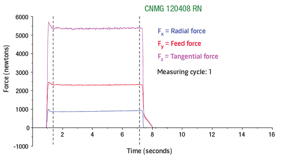
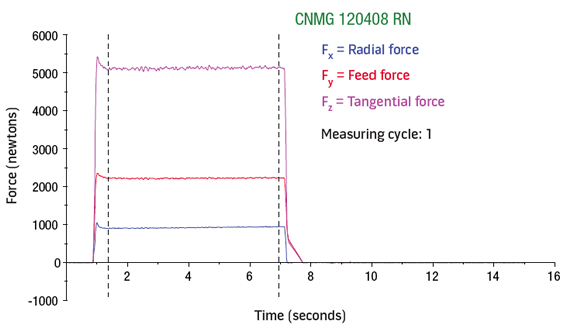
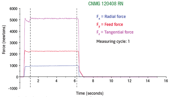
Charts 1 (top), 2 (middle) and 3. Measuring data for roughing output by the dynamometer.
Calculated tangential force FZC = 1,172.42 lbs. (5,215.18 N)
Cutting speed VC = 800 sfm (244 m/min.)
The U.S. units of measurement are:
P = FZC × VC ÷ 33,000 = 1,172.42 × 800 ÷ 33,000 = 28.42 hp
The metric units of measurement are:
P = FZC × VC ÷ 60,000 = 5,215.18 × 244 ÷ 60,000 = 21.21kW
Calculating the power requirement P using UP and mrr is the conventional method.
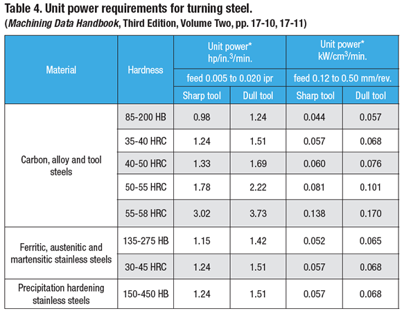
The unit power values for turning on 218-HB alloy steel 4140 (DIN 1.1724) are taken from Table 4.
The U.S. units of measurement are:
P = UP × mrr, where UP = 0.98 hp/in.3/min. (for a sharp tool)
mrr = DOC × f × 12 × VC = 0.200 × 0.020 × 12 × 800 = 38.40 in.3/min.
Power requirement is P = 0.98 × 38.40 = 37.63 hp
The metric units of measurement are:
P = UP × mrr, where UP = 0.044 kW/cm3/min. (for a sharp tool)
mrr = DOC × f × VC = 5.08 × 0.51 × 244 = 632.16 cm3/min.
The power requirement is P = 0.044 × 632.16 = 27.82kW
The results of calculating the power requirements are shown in Table 5, which indicates the conventional method overestimates the power requirements by 32 percent.
Because of a possible patent pending for the method of determining tangential force, the power requirement and a calculator operating in accordance with the method, the formula for the tangential force is not disclosed in this article.
As shown in Table 4, a given unit power value can be used for wide ranges of feed rate and hardness. For example, the unit power of 0.98 hp/in.3/min. is applicable for feed rates from 0.005 to 0.020 ipr and hardness numbers from 85 to 200 HB. The unit power data shown in Table 4 was determined in the late 1970s and those values were based on the cutting tool materials and geometries available at that time. If current cutting tool materials and geometries were used, the unit power values would be 30 to 40 percent lower. Therefore, the conventional method of calculating power requirements is not recommended. CTE
Turning Operation Power Requirement Calculator
Advanced Method (Tangential Force and Cutting Speed)
Tangential Force (FZC) in pounds-force (lbs):
Cutting Speed (VC) in surface feet per minute (sfm):
Power Requirement (hp):
Conventional Method (Unit Power and Material Removal Rate)
Unit Power (UP) in hp/in³/min:
Depth of Cut (DOC) in inches:
Feed Rate (f) in inches per revolution (ipr):
Cutting Speed (VC) in surface feet per minute (sfm):
Power Requirement (hp):
Formulae:
Advanced Method: Power (hp) = (Tangential Force, FZC × Cutting Speed, VC) ÷ 33,000
Conventional Method: Power (hp) = Unit Power, UP × Material Removal Rate, MRR
Where MRR = Depth of Cut (DOC) × Feed Rate (f) × 12 × Cutting Speed (VC)
About the Authors: Edmund Isakov (pictured), Ph.D., is a consultant, writer and frequent CTE contributor. He is the author of the books "Mechanical Properties of Work Materials" (Modern Machine Shop Publications, 2000); "Engineering Formulas for Metalcutting" (Industrial Press, 2004); "Cutting Data for Turning of Steel" (Industrial Press, 2009); the CD-ROM "International System of Units (SI)" (Industrial Press, 2012); and the software "Advanced Metalcutting Calculators" (Industrial Press, 2005). For more information, call (561) 369-4063 or visit www.edmundisakovphd.com. Kent P. Mizgalski is manager product engineering – turning for Kennametal Inc., Latrobe, Pa. Stefan Brand is a staff engineer in global machining technology for Kennametal GmbH, Fürth, Germany. For more information about the toolmaker's products, call (800) 446-7738 or visit www.kennametal.com.

*Calculation of tangential force was performed using the formula developed by Edmund Isakov.

*Calculation of tangential force was performed using the formula developed by Edmund Isakov.
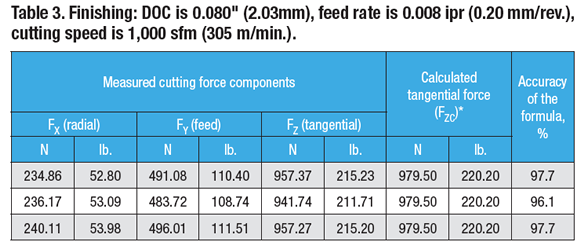
*Calculation of tangential force was performed using the formula developed by Edmund Isakov.
*Power requirements at the spindle drive motor, corrected for 90 percent spindle drive efficiency.


