

A Clean Break: Turning Performance
Parting off presents challenges, but paying attention to the basics makes it a lot easier.
Parting, or cutting, off is a delicate, sometimes dangerous operation. When separating a part from bar stock, the spinning part can fly off and damage the cutting tool or machine. If the blade is misaligned, the part may not separate cleanly or not separate at all, and if the proper tools are not applied, chatter can ruin the surface finish or even break the insert.
However, with proper setup, tooling and fluid application, the cutoff operation is manageable in virtually any machine shop.
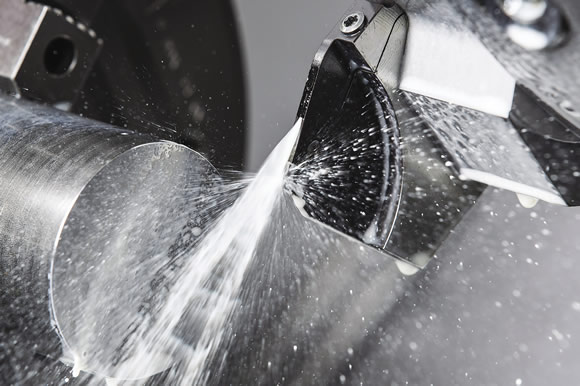
Image courtesy Horn USA.
Machine Matters
An ideal situation for parting off, also known as a “pick-off,” is when the subspindle clamps on the finished end of the part while the main spindle clamps on the bar stock, which keeps both sides of the cut-off operation rigid, reducing risk of the part damaging anything, according to Cooper Ferguson, applications engineer at machine tool builder Okuma America Corp., Charlotte, N.C. However, many machines don’t have a subspindle, so parts catchers are a good alternative. Beyond that, one machine characteristic is important above all others.
“Rigidity is paramount in all areas,” Ferguson said. “If any part of the setup is not rigid, you’ll have chatter, which could scrap your part, throw things out of balance, or potentially damage your tool or machine if the part is ejected. And, of course, you want to make sure you ensure good chip evacuation and don’t exceed the maximum rpm in order to maintain tool life.”
However, machine shops do not exist in a perfect world.
“There are things we, as a tooling company, can control and things we can’t,” said Eric Carbone, applications specialist at Horn USA Inc., Franklin, Tenn. “One of the things we can’t control is the type of machine the customer uses. Ideally, you want the machine tool to be very rigid, but, ultimately, we’re dealing with what they have.” Whether it’s a high-end piece of equipment or an outdated model influences the recommendations a toolmaker provides.
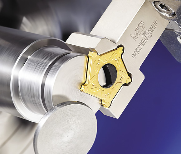
Iscar’s PentaIQGrip parting inserts have five cutting edges and a geometry designed to handle virtually all workpiece materials. Image courtesy Iscar Metals.
The machine itself must be accounted for, but what is done with the machine is more important. According to Clay East, GRIP systems product manager for toolmaker Iscar Metals Inc., Arlington, Texas, tool alignment is the single most important consideration, regardless of the tool or machine.
“The first thing I do when I look at an application is mount the tool and make sure it’s in the correct position,” he said. “Even if you’ve got the best tool in the market, it won’t compensate for misalignment; it won’t compensate for the cutting edge not being where it needs to be.”
Keeping the tool on center is paramount, but the methods for doing so differ depending on the diameter of the bar stock. It’s not a simple set-it-and-forget-it rule.
“For cutting off, you should always use the shortest possible tool length,” said Horn’s Carbone. “If you’re cutting a 4 “-dia. part and your tool is 0.0050 ” off center, that might not be as big of a deal as when the part gets down to 0.5000 “. That difference becomes proportionally much greater.”
With 4 “-dia. (101.6mm) stock, the insert blade must be at least 2 ” long, which creates a lot of potential for the blade to vibrate and flex. “Don’t go any longer than you have to,” Carbone said.
Another consideration for rigidity is insert width. Selecting the widest insert possible without sacrificing material cost will allow for the most support under the insert, creating the best rigidity.
While blade flex is less of an issue with smaller bar stock, it is an important consideration that is often overlooked by machine shops despite being widely recommended by some toolmakers and machine tool builders, according to Carbone. “A lot of manufacturers recommend running small-diameter parts, typically anything under ½ “, slightly above centerline, and most people don’t do that. The theory is you set the insert 0.001 ” to 0.002 ” above centerline, so as you approach zero on your size, the material will start to climb the part. By the end of it, you will be back on centerline.”
Need for Speed
Once the tool is properly centered, it’s time to consider speed. Iscar’s East noted there is a right and a wrong way to measure that speed. Whenever possible, Iscar recommends using surface footage instead of spindle speed.
“Constant surface footage means the contact of the material to the carbide insert is consistent,” he explained. “If you program something for the same surface footage all the way through the cut, it’s going to stay there, and the carbide won’t know if it’s a 4 ” OD or a 1 ” OD, because the material that slides across the carbide will be at the same speed throughout the entire cut. On the flipside, if you program with constant rpm, the closer you get to center, the slower the material will be moving across the cut, which negatively impacts the ability of the insert to plasticize the material.”
However, constant surface footage brings its own risks, noted David Essex, turning product manager for toolmaker Tungaloy America Inc., Arlington Heights, Ill. As the tool goes in toward the center of the spindle, the rpm must increase to maintain a constant surface speed.
“Potentially, the part could fly off and damage the machine tool,” Essex said. “On the other hand, keeping a constant rpm could put more pressure on the cutting tool, shortening insert life and possibly leading to breakage.
“The best practice when you part to center to reduce tool pressure on the cutting edge is to program the job at the suggested feed rate for the particular tool you’re using and feed it down to the diameter that is equal to the width of the insert,” Essex continued. “At that point, you want to reduce your feed rate by 50 to 75 percent. Backing down on that feed rate will minimize pip size, minimize vibration and extend tool life tremendously.”
Additional machine features are available to assist the operation. For instance, Okuma offers spindle synchronization to align the jaws or part features from one side to the other, air blow to clear chips and other debris, and torque skip, which utilizes feedback sensors to indicate when the jaws touch the part and how much pressure is being applied.
Review the print ads from this magazine to continue
This quick advertiser review unlocks the rest of the article and keeps the full-screen reader focused on the ads instead of the page chrome.
Advertisers included in this article experience
Print placements connected to this article
Hornusa
Efficiency Taken to the Extreme
Your solution for reliable production: Triple-edged, indexable inserts for standard and custom tool- ing. Precision-sintered and individually ground features, engineered for efficiency and repeatability. Spe- cially formulated carbide substrates and coatings ensure toughness and wear resistance for long HO R N – E X CE L L E N C E I N T E C H N O L O G Y.
Efficiency Taken to the Extreme Your solution for reliable production: Triple-edged, indexable inserts for standard and custom tool- ing. Precision-sintered and individually ground features, engineered for efficiency and repeatability. Spe- cially formulated carbide substrates and coatings ensure toughness and wear resistance for long tool life, with free cutting geometries to improve process predictability at high cutting speeds. Pro- www.hornusa.com duce more chips with repeatability and efficiency. www.hornusa.com HO R N – E X CE L L E N C E I N T E C H N O L O G Y GROOVING PARTING OFF GROOVE MILLING BROACHING PROFILE MILLING REAMING
Visit Hornusa View this placement in the issue recordPrint ads from this magazine
Your solution for reliable production: Triple-edged, indexable inserts for standard and custom tool- ing. Precision-sintered and individually ground features, engineered for efficiency and repeatability. Spe- cially formulated carbide substrates and coatings ensure toughness and wear resistance for long HO R N – E X CE L L E N C E I N T E C H N O L O G Y.
Efficiency Taken to the Extreme Your solution for reliable production: Triple-edged, indexable inserts for standard and custom tool- ing. Precision-sintered and individually ground features, engineered for efficiency and repeatability. Spe- cially formulated carbide substrates and coatings ensure toughness and wear resistance for long tool life, with free cutting geometries to improve process predictability at high cutting speeds. Pro- www.hornusa.com duce more chips with repeatability and efficiency. www.hornusa.com HO R N – E X CE L L E N C E I N T E C H N O L O G Y GROOVING PARTING OFF GROOVE MILLING BROACHING PROFILE MILLING REAMING
Continue reading
June 2015
“During a pick-off, there’s a lot that the machine has to qualify for each concurrent step,” Ferguson said. “Having all your G and M codes in the proper order is very important, and requires meticulous hand programming.”
Natural Selection
Not surprisingly, selecting the proper tooling depends a lot on part diameter, explained Essex. Block- and blade-type tools have multiple components and maximize adjustability to handle the widest range of part diameters. However, they are not as stable as less-flexible monoblock tooling. Best practice is to select the tool with the shortest overhang possible for the application, he noted.
“You can also have different lead angles on your insert,” Essex said. “A 0° insert will give you a very stable cut, but as you cut deeper and deeper, the material connecting the part to the stock gets thinner and thinner until eventually it just breaks, and then you’ve got a little pip on the part that has to be removed. To address this, a lot of companies offer different lead angles. The idea is that the angle reaches the center of the part before it breaks, minimizing that pip. However, because it exerts a bit of a sideways force on the tool, the angle can affect tool life or surface finish, so it’s a trade-off.”
Another important tool geometry consideration is chip control. According to Horn’s Carbone, the width of the chip must be narrower than the groove made by the insert to avoid chips building up in the slot that’s being cut.
“What happens, especially with large-diameter parts, is the chips get stuck in the groove,” he said. “The chips pack up against the insert, which can cause the insert to break and prevent coolant from getting to the cutting edge. This can reduce tool life and impart a rough surface finish on the side of the part. The way we avoid this is to put a geometry on the insert, a ridge that sticks up or a divot in the middle of the insert, something that bends the chip and makes the chip narrower, making it easier to evacuate from the groove.”
In addition, Carbone continued, older, less-stable machines might require the cutting tool to have certain attributes. For example, an insert with a heavy edge prep will not be as sharp, but it will be strong and stable, more capable of withstanding vibration.
“We might also go with a tougher substrate, a grade of carbide with more cobalt binder,” he explained. “By increasing the amount of binder that’s in the substrate, the carbide can handle more vibration without breaking.”
Ultimately, separating a part from the bar stock requires nothing more than a bar feeder and a blade, but if you know the parameters to control, your operation is bound to be more successful. CTE
About the Author: Evan Jones Thorne is assistant editor for CTE. Contact him at (847) 714-0177 or ejonesthorne@jwr.com.
Keeping the pressure on
While some operations can be run dry or with minimum-quantity lubrication, parting off is best performed with high-pressure coolant, according to Cooper Ferguson at Okuma America Corp.
“As with any other turning or milling operation, coolant will provide the lubricity to let you move through the material more smoothly, and it’ll cool things down, which increases tool life,” he said. “With high-pressure coolant, you get the added benefits of breaking chips sooner and better chip evacuation. Both lead to being able to feed faster, reducing cycle time.”
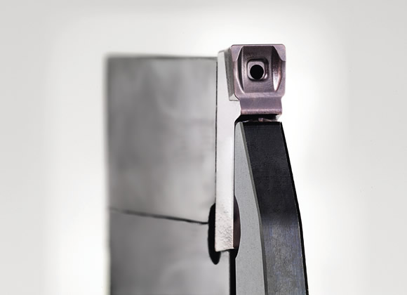
Through-coolant tools direct cutting fluid precisely at the cutting edge. Image courtesy Horn USA.
While there are no coolants formulated specifically for parting off, most toolmakers recommend water-soluble synthetics. Oil’s lubricity extends tool life, according to Eric Carbone at Horn USA Inc., but oil results in slower speeds and feeds and causes a host of cleanliness and rancidity issues. Synthetics have more cooling power, which allows the operation to run faster, and are typically cleaner and easier to manage.
Iscar Metal Inc.’s Clay East agreed. “There’s not a particular type of fluid that we recommend, but the majority of the industry does seem to use water-soluble synthetics,” he said. “If you’re running high-temperature alloys, you want the coolant concentrate to be in the double digits—10 or above on your refractometer. That’s going to give you the best possible tool life.”
Many companies offer through-coolant holders, noted David Essex at Tungaloy America Inc., so fluid is directed to the cutting edge.
“That will do two things: keep your edge cool, which is extremely important for tool life, and help with chip control by evacuating the chips, which improves surface quality. For grooving and parting off, you need to use coolant.”
—E. Jones Thorne
Contributors
Horn USA Inc.
www.hornusa.com
(888) 818-4676
Iscar Metals Inc.
www.iscarmetals.com
(817) 258-3200
Okuma America Corp.
www.okuma.com
(704) 588-7000
Tungaloy America Inc.
wwwtungaloyamerica.com
(888) 554-8394
Glossary terms in this article
Related




Subscribers can use MFGAxis notes, saves and discussion tools with their innoNET account.


