From Maudsley to CNC: The Evolution of Thread Cutting
From Maudsley to CNC: The Evolution of Thread Cutting
A look at the different types of inserts used for single-point threading and how to figure feed rates for cutting threads on a CNC lathe. Also offers programming tips and recommendations for reducing tool wear.
The development of the first modern, industrial screw-cutting lathe occurred in the late 1790s. The man most directly responsible for it was a British toolmaker named Henry Maudsley, who also designed the world's first bench micrometer.
Single-point threading - a fairly simple process - didn't change much from Maudsley's day until the development of the CNC some 170 years later. What controllers did was make single-point threading even simpler.
Throughout history, successful thread cutting has relied on the same basic principle: synchronize the spindle's rotation with the movement of a thread-shaped cutting tool. This is accomplished with a mechanical lead screw and follower on a manual engine lathe. With a CNC machine, computer-controlled servodrive systems perform the same task, albeit much more efficiently.
Point of Contact
You need more than a lathe - manual or CNC - to cut a thread. Tooling, as with any machining process, is a big part of thread cutting.
A threading tool can be as basic as a piece of HSS ground to the shape of the thread profile you wish to cut. For most jobs, of course, an indexable carbide insert is a better choice.
One of the cheapest and most generic inserts available - the so-called utility insert - is a cost-effective choice for less demanding threading tasks. A utility insert is a double-sided, negative-rake threading tool that features four cutting edges for the price of two. But this apparent economy is negated by how the insert is applied.
In order to have four usable edges, the insert is negatively set in the holder. A threading insert tends to be inherently weak because of its unsupported cutting edge. That, coupled with the negative cutting angle, means a utility insert has a much greater tendency to chip than its single-sided cousins. This is especially true when cutting harder materials like stainless steel.
Three other types of threading inserts that are available may provide a better solution for your shop. The first choice is the "on-edge" insert. This style normally has three cutting edges, sits upright in the holder and is held in place by a top clamp and center screw.
The most popular style of threading insert is the "top notch," a nickname derived from the Top Notch brand that was first introduced by Kennametal Inc. A mechanical clamp holds the insert firmly in place by means of a groove molded into its top. Today, the top-notch style is available from a number of vendors.
The "laydown" style is another type of threading tool. As the name implies, it lies flat in the toolholder. A screw or top clamp secures it. Laydown types typically have three cutting edges and require the use of an "anvil," which sits between the insert and holder, supporting the insert and tipping it at a slight angle to accommodate the pitch of the thread.
Regardless of which style you select, you must choose between a full- or partial-profile insert (Figure 1).

Figure 1a: The full-profile insert cuts the flanks and crest of the thread simultaneously. A different insert is needed for every thread pitch. Figure 1b: The partial-profile insert covers a wide range of thread pitches, which reduces the number of inserts that must be stocked.
Partial-profile inserts are by far the more versatile and readily available. They are ground so that the major diameter of the thread (or minor diameter in the case of internal threading) is left uncut by the threading insert. This requires a finishing pass to be made with another tool.
A full-profile insert, as the name implies, cuts the flanks and crest of the thread simultaneously. The entire thread profile is ground into the insert. (Full-profile types are also known as "topping" inserts because they cut all of thread, including the top.)
The main drawback to a full-profile insert is the cost of keeping a large threading-tool inventory. It cuts the entire thread profile, but a different full-profile insert is needed for every thread pitch.
Still, many machinists prefer full-profile inserts because they eliminate the need to recut the crest of the thread, which can save a few seconds of machining time per part. And saving a few seconds per part can trim several hours from a long production run.
Determining Feed
A common problem encountered by machinists during thread cutting is determining the proper feed rate. All CNC machines have feed and rpm limitations that can come into play during thread cutting.
For example, let's say you have to make a part from Inconel that requires machining a 1/2-13 external thread. You know that the proper formula for determining rpm is: (3.82 x sfm)/dia., where sfm equals the cutting speed of the material in feet per minute. You could use that formula or, to simplify things, multiply the cutting speed by four and divide by the workpiece diameter: (4 x sfm)/dia. Either formula is acceptable for this application.
So, you open your Machinery's Handbook and come up with a cutting speed of 60 to 90 sfm for Inconel. Your tooling salesman would probably suggest a much higher cutting speed, but, for this example, let's be conservative and settle on 75 sfm. You solve for the required rpm: (4 x 75)/0.5" = 600 rpm.
The next step is to program the CNC to start the spindle in the rpm mode with this command: G97 M3 S600. Now that you have the spindle turning at the proper rpm, it is time to calculate the feed rate.
Calculating the feed rate for any thread is simple. Just grab your calculator, enter the number 1 and divide it by the number of threads per inch. The resulting value is the lead of the thread, or how far the screw thread advances in a single revolution of the chuck. In our case, 1 divided by 13 equals 0.076923". Rounding to the four decimal places required by the machine control gives you a feed-rate value of 0.0769 ipr.
So, now that the machine is programmed, you push the cycle-start button and go on your merry way, cutting threads in Inconel.
But what if the material is changed to 6061-T6 aluminum. No problem, right? Let's see.
The cutting speed for 6061 is somewhere in the 1,000- to 1,200-sfm range, meaning the spindle speed is in the neighborhood of 8,000 to 9,600 rpm. You know that your machine spindle won't go that fast, so you settle for 600 sfm, which requires a spindle speed of 4,800 rpm: (4 x 600)/0.5". Obviously, the feed rate doesn't need to change because you're cutting the same thread pitch. So you input G97 M3 S4800 to get the spindle turning, G76 or G92 for the threading cycle and finally input a feed-rate value of 0.0769 ipr (F.0769). No big deal, right? Wrong!
What you've failed to realize is that although your spindle may be able to rotate at 5,000 rpm, your machine won't be able to feed fast enough. Many of today's CNCs, despite their advanced technology, are limited to a maximum feed rate of roughly 150 to 200 ipm.
In any machine program that feeds in ipr, the CNC ties the machine's feed rate directly to the spindle rpm. As spindle speed increases, so does the machine's velocity, or the feed rate in ipm, just multiply feed rate (in ipr) x rpm. This formula is important because if you attempt to cut a 1/2-13 thread at 4,800 rpm, as in our aluminum thread-cutting example, you are telling the machine to feed at over 369 ipm, far beyond its capability.
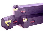
An on-edge threading insert (left) and two laydown types. They offer advantages over utility inserts.
Most lathe operators program their feed rates in ipr, while mill operators tend to program feed in ipm. To convert ipr to ipm, just multiply feed rate (in ipr) 5 rpm. This formula is important
An on-edge threading insert (left) and two laydown types. They offer advantages over utility inserts.
Countering Tool Wear
A CNC's feed-rate limitation can cause some real problems for a machinist. It can lead to tool-life problems, bad threads and poor productivity. Built-up edge, tearing and insert chipping are common symptoms of insufficient surface speed when running carbide tools.
The machine operator could increase the surface speed (rpm), but, as we've just seen, this isn't always possible. Therefore, the machinist must find other ways to solve the problem, such as using an alternate carbide grade or by making a programming change.
One solution to tool-life problems is to use an angled threading pass. Those of you who have performed single-point threading on an engine lathe probably recall adjusting the compound slide so that it sat at a 29.5° angle. A manual-lathe machinist controls the depth of the thread by infeeding the tool at this angle. Cutting a thread in this fashion forces the leading edge of the threading tool to do most of the work. It also greatly reduces tool pressure and generally improves tool life.

A mechanical clamp holds the top-notch insert firmly in place by means of a groove molded into its top.
A mechanical clamp holds the top-notch insert firmly in place by means of a groove molded into its top.
Single-point threading on a CNC lathe is no different except, of course, the machine has no compound slide. The angled infeed generated on a manual lathe with a tipped compound slide must be accomplished on a CNC machine tool through programming techniques.
Programming an angled infeed is usually a simple task. Any of today's CNCs will allow you to simply change a parameter in the control or, easier yet, just alter a value in the program. The CNC's programming manual will indicate the correct value to change.
This simple programming adjustment is much easier than loosening bolts, changing tools and swinging compound slides to odd angles. Indeed, CNC lathes make single-point threading so easy that any machinist who has mastered it might find it difficult to go back to an engine lathe.
Since Maudsley's screw-cutting lathe, machining screw threads has become an even simpler machining operation. What once was the purview of skilled craftsmen is now something that any machinist can do - providing he has a programming manual and pocket calculator.
About the Author
Kip Hanson, a regular contributor to CTE, is general manager of Allen Co., Edina, Minn.


