Frenzied Feeding
Frenzied Feeding
By changing the nose radius of their finish-turning inserts, toolmakers are producing wiper inserts that allow machinists to turn workpieces at increased feed rates. This article explains the theory behind this innovation and describes the specific wiper-style geometries employed by three manufacturers.
Up until now, high-speed machining has gotten all the press. Touted as a way for machinists to cut through a workpiece faster, high-speed machining—or more specifically, high-speed milling—has been discussed, explained, analyzed, and evaluated dozens of times in print. To increase throughput, according to conventional wisdom, boost spindle speeds. And in recent years, the market has responded with a variety of tools and spindles that allow machinists to make chips at speeds of well above 10,000 rpm. Some industry visionaries are predicting that one day spindle speeds of 100,000 rpm will be commonplace.
However, in the realm of finish turning, there has been growing interest in a different strategy for maximizing productivity. Some cutting tool manufacturers are saying that it is possible to increase feed rates without increasing spindle speeds. According to these experts, machinists can boost their tools' feed per revolution and still achieve the fine surface finish called for in the part specifications.
Breaking the Feed Limit
In finish turning, the feed rate has always been limited. It's a simple matter of geometry. If the tool moves farther than the width of its cutting edge in one revolution of the workpiece, material is left uncut. As the feed rate increases, the gap of uncut material increases as well. "You actually start cutting a thread, for lack of a better word," says Michael Gadzinski, national training director for Iscar Metals Inc., Arlington, TX. "You get a wave type of a pattern."
Because this waviness can be tolerated in a roughing operation, rough-turning feed rates are higher. But when finish turning, machinists must reduce feed rates to avoid leaving a pattern. In fact, the purpose of a finishing operation is generally to remove the waviness that rough turning leaves. Sometimes, even a slow feed rate and a light depth of cut (DOC) cannot produce a surface finish good enough to meet specifications. In these cases, the shop must rely on a finish-grinding step.
With either turning or grinding, the finishing step represents a large investment of the shop's time. Reducing this time by speeding up the operation is the objective that shops are seeking with high-feed turning.
Theoretically, a machinist can use a tool with a larger nose radius to increase the feed rate and still obtain a smooth surface finish. The larger radius presents a broader cutting edge to the workpiece, so the tool can move farther per workpiece revolution and still overlap the cut made in the previous revolution. The handbook Modern Metal Cutting, published by Sandvik Coromant Co., Fair Lawn, NJ, says a 0.016" nose radius at a feed of 0.010 ipr will produce a profile height of 20.0µm, while a nose radius of 0.094" will produce a height of 3.3µm at the same feed rate.
But increasing the nose radius to achieve a larger feed rate has its limits, too. Tools with larger nose radii are more likely to begin vibrating in the cut. A larger nose radius also inhibits a tool's ability to break chips and may require a deeper DOC to engage the cutting edge properly.
A few toolmakers believe that they have found a solution that overcomes the limitations that geometry imposes on finish-turning operations. Taking a page from the milling-insert design book, they've modified the nose geometry of their tools to produce finish-turning wiper inserts.
Wiping Out Waves
A standard insert, regardless of its nose radius, has a smoothly curved tip, with a line that curves around at a consistent radius. By contrast, a wiper insert's nose is slightly flattened. Manufacturers describe this geometry as a combination or a blend of radii. Iscar was one of the first to offer this type of cutting tool. It originally introduced the design in 1991, according to Gadzinski, and it has been modifying and improving upon it ever since. "The idea behind the wiper is similar to what we use on a milling-cutter insert," Gadzinski says. The design is a modification of the pure 80° angle of a CNMG or a trigon-style insert. "Approximately 0.030" to 0.040" behind the corner it switches itself back out to about 85° to 88°," Gadzinski explains (Figure 1).
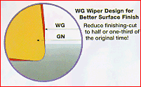
Figure 1: The darker area on this diagram shows the modified angle Iscar uses to turn a standard GN inserts geometry into a WG wiper inset's geometry.
Mark Alig, turning product specialist for Sandvik, describes the nose geometry of the finish-turning wiper insert that his company introduced last year as a "blended" radius. The edge of the insert essentially traces a path around the edge of two overlapping circles, leaving the tip with a slightly elliptical shape.
Carboloy Inc., Warren, MI, introduced a polycrystalline-cubic-boron-nitride (PCBN) wiper insert last year. The company plans to introduce a carbide version in April. Bob Goulding, stationary tooling manager for Carboloy, says that his company's inserts differ slightly from other wipers on the market. Other manufacturers have reduced the radius of the actual leading edge of the tool, letting the modified, truncated geometry of the tip do the work instead. Carboloy, on the other hand, has inserted a larger radius into the curve of the tip. A brochure for the carbide version illustrates the tool's design concept with a diagram showing two round inserts morphing into a rhombic insert. According to Goulding, this geometry allows users to continue finish turning with the familiar C and W insert shapes. But they can achieve higher performance with these inserts because the larger radius inserted into the geometry gives the tool many of the characteristics of a round insert.
The idea behind all of these inserts is similar. The trailing edge behind the primary cutting edge wipes or smears the wave pattern that is left behind by the quickly moving insert (Figure 2). "The blended radii knock off the high points created by the feed lines," says Sandvik's Alig. "This provides a smoother finish without utilizing a larger nose radius or slower feeds."
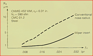
Figure 2: This graph comparing the performance of a wiper insert to that of an insert with a standard nose radius shows how a wiper insert can produce better finishes at various feed rates.
All three manufacturers have designed their wiper inserts to be high-feed tools for use at light DOCs. With their wiper-insert designs, each company has taken into account the higher chipload that is generated at elevated feeds. Iscar's Gadzinski says the wiper inserts he's seen have been designed with very aggressive chipbreakers. According to Sandvik's literature, the chipbreaker on its wiper insert "extends well beyond normal cutting-data limitations."
Feed vs. Finish
These new wiper designs give machinists a choice. "With a wiper, if you leave cutting data the same, you can achieve a much better surface finish," says Carboloy's Goulding (Figure 3). He gives the example of a wiper insert cutting at a feed rate of 0.012 ipr. The operation will produce a surface finish of 15µin. to 18µin. Ra, he claims. Goulding says a standard insert with a 0.030" nose radius at the same feed rate will produce an 80µin. Ra. "But," he adds, "you have the opportunity, especially in medium roughing, for example, of doubling or increasing the feed rate but retaining the same surface finish you had before. The benefit there is productivity." According to Goulding, if the feed rate is increased to 0.020 ipr, Carboloy's wiper insert will produce a 20µin. Ra surface finish. At that feed, a standard insert produces a finish of 200µin. Ra.
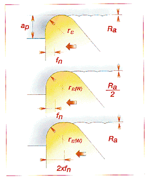
Figure 3: These diagrams compare the performance of a standard insert (a) to that of a wiper insert (b) and (c). Even though the leading-edge nose radius (re) remains the same, the wiper inserts can produce half the surface roughness (Ra) at the same feed (f), or the equivalent surface roughness at double the feed rate.
With such dramatic gains in surface finish, shops may be able to achieve on a lathe what they once needed secondary operations to achieve. As an example, one automotive manufacturer was able to eliminate a grinding step by finish turning brake rotors using Carboloy's PCBN wiper inserts. Before using the inserts to machine the rotors, the manufacturer would have to move the parts from the lathe to a grinding machine to finish-grind them, says Goulding. The company's machinists are now able to rough- and finish-turn the parts on the same machine. Goulding cautions that it still may be necessary to grind parts for dimensional precision. But if the grinding is simply to achieve a high degree of surface finish, finish turning with wiper inserts may be a reasonable alternative.
In studying the performance of their wiper inserts, the toolmakers claim to have discovered some side benefits besides higher feed rates and better surface finishes. All three claim their wiper inserts last longer than conventional inserts, even though they were not necessarily designed for extended wear. According to Gadzinski, the truncated angle at the tip of a wiper insert adds strength. Iscar tested its inserts by turning stock with a hexagonal cross section. Despite the highly interrupted cut, Gadzinski says, the inserts resisted breakage and wear longer than conventional inserts. Sandvik's Alig says that the longer tool life is due to the shape of the tool's tip, which keeps the cutting forces from damaging the part of the insert that smoothes the workpiece surface. "The main cutting edge performs the brunt of the work," he explains. "The wiper is protected, yet it is responsible for the critical factors of finish."
Sandvik's literature also says using wiper inserts can keep cutting temperatures down. The higher feed rate reduces the amount of time the tool is in the cut. Therefore, there is less time for the operation to generate heat. Because the operation runs cooler naturally, says an article in Sandvik's in-house magazine, Metalworking World, it may be possible to machine a wider range of parts without coolant when wiper inserts are used.
An Easy Transition
Machinists should be able to make the transition to wiper inserts relatively easily, according to the toolmakers' representatives. The grades of wiper inserts available are similar to the standard insert grades toolmakers offer. "If you were to use a 4025 grade with a PM insert, use 4025 with WM," says Alig. The toolmakers are not producing the inserts in as wide a selection as their standard inserts, however. Sandvik, for instance, is only offering two chipbreaker styles. Iscar's Gadzinski says the limited selection is due to the relatively small market for these inserts at present. Typically, he says, wipers are being offered in the harder grades that are appropriate for higher cutting speeds. He says Iscar's selection includes a cermet that can be used on steels and cast irons because it resists built-up edge, and tougher carbides for stainless steels and other materials that produce a lot of pressure and heat. Sandvik also offers its inserts in cermet and carbide grades.
In the shop, few changes will be required to machine with the new inserts. Gadzinski says that users can finish-turn parts at the same speeds and DOCs that they are using with standard inserts. The only change needed is an increase in the feed rate, and this, he says, is necessary to take advantage of the insert's ability to save the shop time and money.
Goulding says that wiper inserts can be used on any lathe or turning center. Unlike high-speed milling, high-feed turning does not require a machine with significantly more horsepower or rigidity. Some adjustments will be needed, however. Alig says high-feed turning with a wiper insert will cause a 5% increase in tool pressure. "But you can compensate for this by dropping down to a smaller nose radius," he says. Alig also suggests that users review the tool manufacturers' literature to make sure their machines have the horsepower needed for the feed, nose radius, and DOC they want to use.
According to Alig, there are some applications that are not suited for wiper inserts. "Wipers are typically not recommended for long and slender shafts, thin-wall components, or parts with a taper greater than 5°, because you lose contact with the part," he says. Sandvik's literature also says that the inserts are not intended for profiling cuts. Although the tools are capable of machining shapes other than straight-line geometries, the wiper effect works best when the tool's lead angle, relative to the direction of feed, is -5° to +10°.
The big question in all of this is whether the concept of high-feed turning will catch on. Gadzinski says that the acceptance of high-feed turning has been frustratingly slow, but he hopes that the growing competition in the wiper market bodes well for the concept. With the increase of products and promotion, he says, users just might start to realize that there is technology out there that can boost their finish-turning productivity.


