



Hard Prep: Turning Performance
Various edge preparations are available for PCBN inserts when hard turning, but not all are equal.
Various edge preparations are available for PCBN inserts when hard turning, but not all are equal.
Parts manufacturers face a conundrum when finishing hardened workpieces. Hard turning is often considered a more flexible, more environmentally benign and higher throughput alternative to grinding. However, grinding is a more reliable process and imparts a higher quality surface finish than hard turning because of issues related to a cutting tool’s geometry, according to Tuğrul Özel, associate professor at Rutgers University’s Department of Industrial and Systems Engineering.
Users typically apply PCBN insert tools when hard turning because the tool material is harder than carbide. Also, PCBN doesn’t chemically react with ferrous workpieces when cutting them and produce premature tool failure as does PCD.
PCBN tools can withstand the high temperatures associated with hard turning, but PCBN’s metal binder material softens and then fails after the cutting temperature exceeds about 1,200° C, Özel noted.
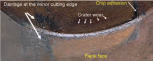
He added that flank wear, which occurs at the flank face of the minor cutting edge, is followed by crater wear, which predominantly forms on the rake face near the major cutting edge, and edge chipping, which can lead to catastrophic tool failure. To improve the productivity and reliability of hard turning with PCBN tools, impart finer surface finishes and protect the cutting edge—especially around the insert nose—an optimal edge preparation is required.
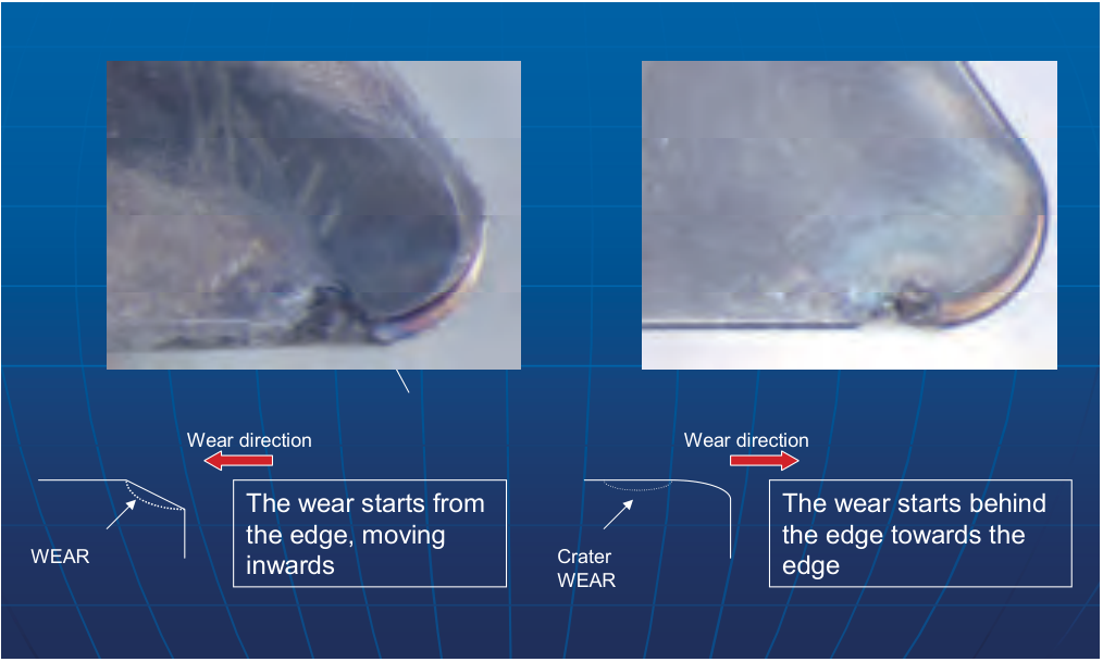
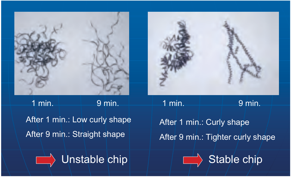
Courtesy of Conicity Technologies
Cutting tests conducted by Conicity Technologies show tool wear and its direction on PCBN DNGW 150608 inserts with a standard T-land edge preparation (upper left) and Conicity’s waterfall edge preparation (upper right). In addition, the T-land insert produced unstable chip chips (lower left) and the waterfall insert created stable chips (lower right).
Edge Prep Options
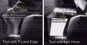
Toolmakers try to apply an edge preparation uniform in size and shape on all cutting edges, typically a T-land chamfer or radial style, according to Bill Shaffer, vice president of Conicity Technologies LLC, Latrobe, Pa., a provider of cutting tool edge preparation equipment. A T-land chamfer is the most common edge prep, he added, but while effective at minimizing chipping it presents an “extremely” negative surface to the workpiece, with the cutting corner looking more like a plow than a cutting edge. “With the cutting edge assuming a negative position, the chip being separated from the workpiece exits and basically dives directly into the face of the T-land,” Shaffer said. “That is one of the reasons a T-land tool will fail due to cratering of the cutting edge.”
Shaffer noted that cratering causes two types of tool failure. If a crater is deep enough, a chip can drive into the tool and fracture directly in line with the cutting forces—vertically down the tool’s flank side. Or, if a crater allows a chip to become lodged, the cutting forces become horizontal and fracture the PCBN by cleaving the rake face surface of the tool.
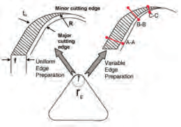
Courtesy of T. Özel et al
A comparison of a uniform edge preparation and a variable edge preparation.
Unlike a T-land, which causes wear to begin at the cutting edge and move toward the center of the tool, a waterfall, or oval, corner profile having a variable edge preparation causes the wear to begin away from the cutting edge and move toward the edge, Shaffer explained. “This delays the distortion of the cutting edge and allows a higher level of chip control,” he said, adding that chips hug the top of an insert with a waterfall hone and effectively exit the cutting zone.
In contrast, chips get pinched between the tool and workpiece and exit vertically with a T-land tool. “There is no real exit avenue for chips with this edge geometry,” Shaffer said.
Compared to a standard radial hone that keeps cutting forces isolated on the tool tangency, the oval geometric profile directs cutting forces off the tangency and deeper into the tool, which reduces tool pressure, according to Shaffer. In tests and hard turning applications, waterfall edge geometry reduced tool pressure as much as 40 percent, he reported.
Very Able Edge
Shaffer added that with a waterfall hone’s variable edge preparation, a tool is edge prepped based on the way it is going to be applied to cut, where the primary, or leading, cutting edge is a specific size based on the feed rate. As the cutting edge transitions around the nose radius, the edge prep decreases in size until it is essentially sharp at the tangency of the nose radius and the adjacent cutting edge, which takes a “trace” cut, he noted. “Chip load thickness naturally decreases as the nose radius turns away from the primary line of cut.”
In an Elsevier paper titled “Hard turning with variable micro-geometry PcBN tools” by Özel et al., results from experimental and finite element modeling showed that inserts with a variable edge prep reduced heat generation, induced less plastic strain on the workpiece and had less wear than similar tools with a uniform edge preparation when turning AISI 4340 steel hardened to 40 HRC if the variable edge was properly designed for the given cutting conditions. In addition, PCBN inserts prepped with a waterfall hone having edge radii that varied from 30µm to 60µm yielded the lowest radial forces at a cutting speed of 125 m/min., a feed of 0.15 mm/rev. and a DOC of 1mm, the paper stated.
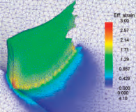
Courtesy of T. Özel et al
Simulated chip formation and strain fields for a PCBN insert with a waterfall hone after 0.5 milliseconds when cutting AISI 4340 steel hardened to 40 HRC at a cutting speed of 300 m/min., a feed rate of 0.15 mm/rev. and a DOC of 1mm.
Courtesy of T. Özel et al
The wear modes for a PCBN insert with a waterfall hone having edge radii that vary from 30µm to 60µm after cutting AISI 4340 steel hardened to 40 HRC at a cutting speed of 300 m/min., a feed rate of 0.15 mm/rev. and a DOC of 1mm.
According to Özel, those results occurred because a PCBN insert with variable edge prep provides more shearing rather than plowing action when hard turning. That’s because a uniform geometry along the insert corner creates a low uncut-chip-thickness-to-edge-radius ratio at the minor cutting edge where the uncut chip thickness becomes small. “The work material gets trapped near the end of the uncut chip geometry along the corner radius,” he said. “Inefficient cutting increases strains in the workpiece, which in turn increases mechanical and thermal loads and produces extreme heat.”
Shaffer elaborated that the thickness of the uncut chip equals the size of the uniformly applied edge prep at a point that is typically in the middle of the tool nose radius. From that point forward, the edge prep exceeds the thickness of the uncut chip, and the uncut chip is compressed between the tool and workpiece instead of being cut. “Tool pressures increase and tool efficiency decreases,” he said. “The energy being spent to cut the workpiece is transformed into heat from tool rubbing.”
The variable edge prep also eases pressure on the workpiece and enables hard turning at higher cutting speeds and feeds with less tool wear, Özel added. He noted that the edge prep is also effective when turning titanium and nickel-base alloys in addition to hardened steel.
Applying the Technology
Several metals exist that are suitable to be hard turned with variable edge-prepped PCBN inserts, including highly alloyed P/M materials, according to Federal-Mogul Corp., which develops those proprietary alloys for engine components, such as valve seat inserts for engine heads. Denis Christopherson, global R&D manager of the Valve Seats and Guide Group at Federal-Mogul’s facility in Waupun, Wis., noted that the materials can be composites of high-alloy steels and hard particles, including ceramics and cobalt-based additives. “We work with fairly exotic materials. They are not industry standard,” he said, adding that material hardness can be up to 70 HRA and harder, with particle hardness higher than 1,000 HV.
Courtesy of Federal-Mogul
Still images from a high-speed video illustrate the chip flow difference between a tool with a T-land edge and one with a light hone.
The high-alloy materials provide the high temperature and wear resistance required for the increasingly aggressive environments experienced by valve seat inserts as engines become smaller, higher revving and hotter. However, as the company develops metals that are up to the task, it sees a shrinking sweet spot, or safe zone, for robust machining processes and consistent tool wear, increasing the risk of fracturing or cratering when hard turning.
“It’s problematic because we’re engineering materials for greater durability, which typically leads to poorer machinability,” Christopherson said.
He noted, however, that machinability is not a material property but rather a material’s response to a machining process. Therefore, when the material is a challenge to machine, the machining system must be rigid and well designed to effectively produce chips, and the user must follow good machining practices, Christopherson explained. He added that controlling those elements enlarges the sweet spot. And a PCBN insert’s edge prep is part of that system. “The edge prep can be very potent in the success or failure,” he said. He added that a micro-engineered edge prep isn’t always critical but becomes more important as the process becomes more sensitive.
Courtesy of Federal-Mogul
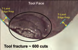
Federal-Mogul reported that fracture occurred, eliminating the tool’s T-land edge, after about 600 cuts during a machinability test. Cutting force and acoustic frequency values immediately dropped because chip pinching on the T-land edge was eliminated. Surface finish values also dropped, suggesting easier chip formation and flow across the tool face. Although a fractured edge is not a desirable condition, the event illustrates the impact of a T-land edge preparation on the cutting forces, vibrations and chip flow during machining.
Christopherson primarily works with OEMs to develop processes to machine Federal-Mogul’s materials. The heat-treated valve seat inserts are machined in the engine heads to provide the best valve mating surface, and hard turning and reaming are often performed on the same spindle to minimize runout and achieve proper alignment between the valve guide hole and insert seat face, he noted.
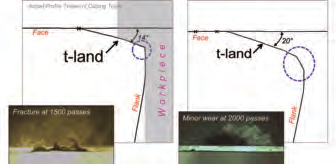
Plunge cutting is the most common machining operation for valve seat inserts. That generates varying chip thicknesses and loads throughout the cut and tends to promote chipping or notching of the cutting edge, so a lot of the R&D group’s work focuses on the cutting edge, Christopherson pointed out. Although a T-land pushes material and increases cutting forces, it may be necessary for edge strength. Whether or not a T-land chamfer is used, an engineered edge break transition is important to eliminate a weak “dead sharp” condition, he explained.
Even with a rigid setup, however, the high cutting forces from driving chips into the T-land face generate small vibrations, which can be seen with the company’s high-speed video system. (To view samples of Federal-Mogul’s high-speed videos, click here.)
Courtesy of Federal-Mogul
Changing an insert’s T-land angle and flank transition profile made the difference between success and failure.
“We’ve shown a 900Hz microvibration with a ¾ “-dia. boring bar in a very rigid CNC machining center when running a T-land,” Christopherson said. “When we run a simple hone and get the chip to flow smoothly across the face of the tool instead of pinching, it’s a nice, quiet, steady, no-vibration condition.”
When a standard edge prep from a toolmaker won’t do, Christopherson enlists a cutting tool edge supplier to provide special edge preps, such as a waterfall design. “I haven’t found too many people who can do a waterfall hone well,” he said.
Even the correct edge prep, however, can’t overcome a weak machining system. “If you’ve got poor rigidity, poor setup, poor design of the workholding and toolholding, and then ask me for 10,000 cuts on a high-alloy material, it isn’t going to happen,” Christopherson said. “You need to build a strong foundation.” CTE
About the Author: Alan Richter is editor of CTE, having joined the publication in 2000. Contact him at (847) 714-0175 or alanr@jwr.com.
Variable edge preps and tool coatings
Most cutting tools with a variable edge preparation are uncoated, but a coating can provide additional machining benefits, according to Rutgers University’s Tu˘grul Özel. That’s because a coating can resist heat, enhance lubricity, increase hardness and provide wear indication, depending on the type of coating. However, applying a coating blunts and dulls edge geometry because, for example, a coating’s thickness turns a 5µm edge radius into a 10µm or 15µm one, Özel added.
To overcome that, an edge preparation can be added onto a coated tool, he noted. “The coating becomes thinner, of course, because you are putting edge preparations on, say, a 5µm- or 10µm-thick coating,” Özel said.
Conicity Technologies’ Bill Shaffer noted that his company has provided a variety of edge preps on coated carbide tools but has not yet edge prepped coated PCBN tools.
Özel added that he and Conicity, along with various research institutes, Seco Tools and the toolmaker’s coating division, are participating in an international study conducted among the members of The International Academy for Production Engineering (CIRP) to investigate the influence of putting an edge preparation on a coated tool and determine which method achieves the best tool life and productivity gains. “We will probably have the results in about a year because there are various companies participating,” he said.
—A. Richter
Contributors
Conicity Technologies LLC
(877) 752-6132
www.conicity.com
Federal-Mogul Corp.
(248) 354-7700
www.federalmogul.com
Rutgers University, Department of Industrial and Systems Engineering
(732) 445-3654
www.ise.rutgers.edu
Glossary terms in this article
Related




Subscribers can use MFGAxis notes, saves and discussion tools with their innoNET account.


