



Hidden gems: Drilling Performance
Courtesy of All images: Walter USA
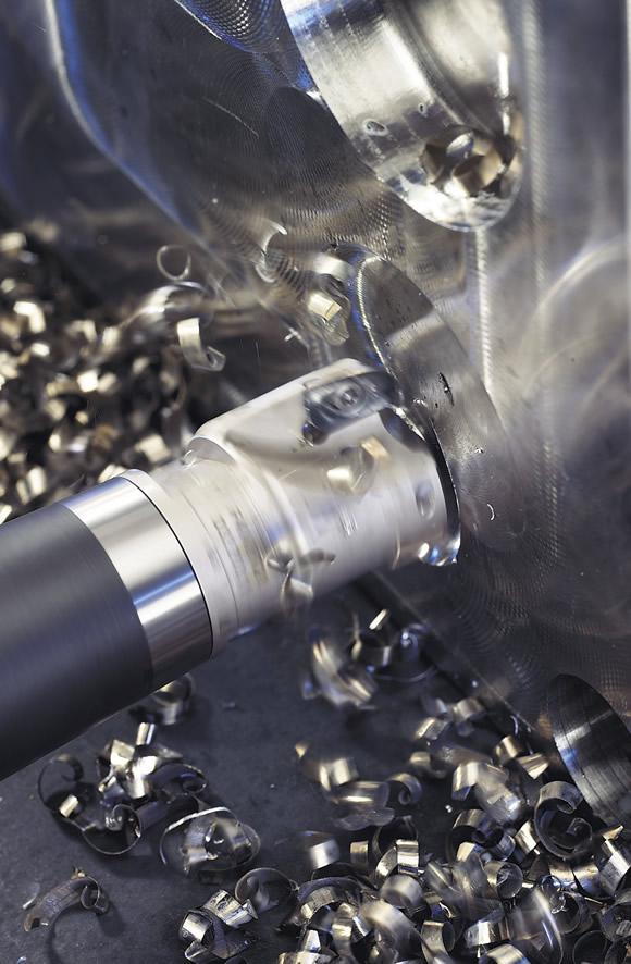
Courtesy of All images: Walter USA
Applying indexable-insert cutting tools on relatively small, multipurpose machine tools, instead of dedicated machines, can make machining a challenge.
Most mass-produced parts were once made on dedicated machine tools. These machines were often built on massive castings, only operated along one axis and expensive. Spindle speeds were relatively slow and material-removal rates high. Cutting tool designs that may have worked on those dedicated machines may not be effective on today’s smaller, multipurpose CNC machines.
To keep production costs down, part manufacturers often buy the least expensive CNC machine tool they can. These machines are often smaller than a manufacturer would like. In many cases, the spindles are small, including the tooling interfaces. CAT 40 tapers or HSK-63 shanks, for example, are less expensive than their larger CAT 50 or HSK-100 counterparts.
Multipurpose machines typically have higher spindle speeds, take lighter stock removal and produce parts with tighter tolerances than dedicated machines. Misapplication of standard and custom indexable tools on multipurpose machines produces unsatisfactory results.
However, following some simple guidelines can markedly improve the results shops can achieve with a smaller, multipurpose machine and indexable-insert cutting tools. This article examines five commonly overlooked factors that can affect tool performance on these machine tools: machine horsepower, a tool’s length-to-diameter ratio, part finish and number of cutting edges, fine tool adjustment and tool balancing.
Know Your Power
If a surface can be milled in 6 minutes with eight effective teeth, can the same surface be milled in 3 minutes with 16 effective teeth? Not always.
Many machine tools have disappointed users because of their limited available horsepower. Users should expect to realize only 80 percent of an electric motor’s rated horsepower because of efficiency losses through the drive components. Most machine tool builders list usable horsepower in their manuals, but, if going by the rating of the motor alone, users should expect about a 20 percent reduction. Keep in mind that most machines can provide more than 100 percent of their available horsepower for short periods, which varies based on the machine, because of stored kinetic energy.
One way to determine if there is enough horsepower for a given operation is to calculate the cubic inches of material being removed in 1 minute. In other words, take the cross-sectional area of the part to be cut multiplied by the feed rate in inches per minute. When cutting steel, for example, 1 hp can typically remove 1 in.3/min. Cast iron, depending on its composition, requires about 20 percent less power, and aluminum needs about 65 percent less power than steel. Exotic materials, however, need more power to be cut. It should be noted many other factors influence actual horsepower requirements.
For a boring operation, the formula for horsepower to calculate the cubic inches of material being removed in 1 minute is:
hp = [(finish diameter ÷ 2)² × π – (prebored diameter ÷ 2)² × π] × ipm
For a drilling operation, use zero as the prebored diameter.
Inadequate horsepower can produce chatter or stop the spindle. If horsepower limits are exceeded for a prolonged period, the machine may automatically perform an emergency stop. This typically destroys a tool’s cutting edges.
Related to horsepower is available torque. When reducing the spindle speed, such as when attempting to eliminate chatter, the spindle can stall. Consult a machine’s torque curve before running at a low speed.
Not Too Long
Another overlooked area that influences indexable-insert tool performance in multipurpose machine tools is a tool’s length-to-diameter ratio. When boring, for example, the relationship of the distance from the insert tip to the smallest diameter of the tool body is the length-to-diameter ratio. It is not simply boring depth divided by boring diameter. Many tools may have a diameter smaller than their cutting diameter somewhere along the tool body. This smallest diameter is where the tool will deflect.
For steel tool bodies, anything above a 4:1 ratio can cause trouble, usually in the form of chatter or excessive deflection. Tool bodies made of heavy-metal or Mallory materials can perform well up to a 7:1 ratio, and solid-carbide tool bodies are suitable up to a 12:1 ratio. Similar ratios apply for milling tools with extended-reach adapters.
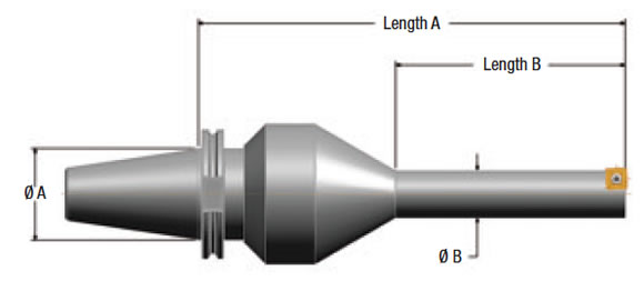
Figure 1. A tool assembly with two length-to-diameter ratios.
An important tool-performance consideration is the highest length-to-diameter ratio found on the tool. Figure 1 shows two such ratios: length A/diameter A and length B/diameter B.
Consider an example in which length A is 8 ” and diameter A is 1.75 ” (4.57:1), while length B is 4 ” and diameter B is 1.0 ” (4:1). While the diameter B looks small and troublesome, it is actually the gage line diameter that is the limiting factor. A larger connection—say, a CAT 50 instead of CAT 40—would help by reducing the length-to-diameter ratio, thereby adding stiffness to the tool.
The Right Finish
The finest surface finishes are typically imparted with a single-point, or “fly,” cutting tool. However, this application is rarely practical unless only one or two parts need to be machined and time is not a factor, because a single-tooth tool can only run at a low feed rate.
When applying standard inserted tools, surface finish is determined by the corner radius of the insert, lead angle of the tool and feed per revolution. With a single-point tool, surface finish can be accurately calculated. Unfortunately, a multi- point tool produces a rougher surface because of runout caused by the multiple cutting points. Of course, an adjustable tool can reduce runout.
However, the runout of the setting device itself, which generates error, and the runout of the machine spindle will limit how fine a finish can be realized, even with a tool that has been carefully set up (Figure 2).
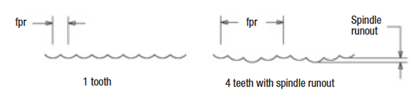
Figure 2. Runout of the setting device and runout of the machine spindle limit how fine a surface finish can be imparted. The form shown is the finish imparted as the inserts cut across the part, and fpr is the feed per revolution.
It is common practice to use wiper-flatted inserts to improve surface finish when applying tools with multiple cutting edges. With a wiper insert, the insert is usually set 0.001 ” (25µm) above the other inserts so it is the only insert leaving a feed line on the part. To get good results, the feed per revolution must not exceed the length of the wiper flat on the insert.
Fine Adjustment
When the position, such as a milled surface, or size of a machined surface is critical, it may be helpful for the cutting tool to have a fine-adjustment feature. When boring, for example, diameter adjustment is required when half of the part tolerance is less than the total possible error in the boring tool. In reality, most manufacturers cut the required part tolerance in half to achieve process capability, commonly called the “capability index” or Cpk.
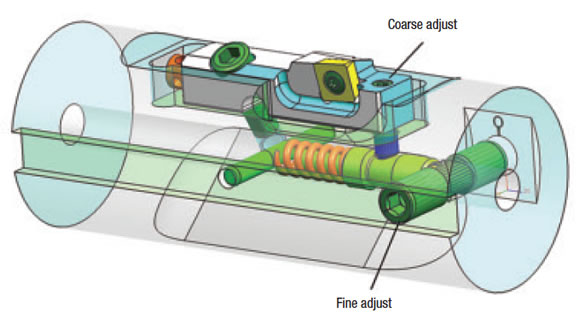
Figure 3. A coarse-adjustment mechanism and a “clicker” fine-adjustment mechanism used in a line-boring bar to finish bore the crankshaft journals in an engine block.
Fixed-insert pockets in indexable tools can only be expected to be positioned within ±0.001 ” (25µm) of their intended location in the tool body. Total possible error equals pocket tolerance plus the tolerance of the insert’s inscribed circle. When boring, multiply this error by two because the error is on radius and the machine is cutting a diameter. If the total possible error is greater than the required part tolerance, an adjustment is needed.
A simple adjustment, like a radial screw in an ISO-style cartridge, can realistically achieve tolerances of ±0.001 ” (25µm) on diameter. However, a gage or setting device is required to measure the adjustment. Many milling cutters also have some type of adjustment to set insert position.
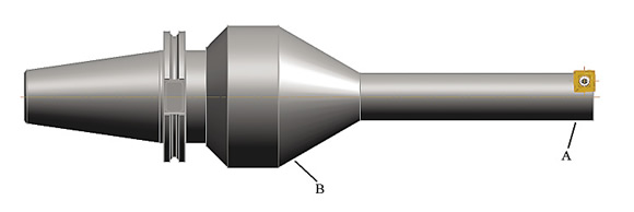
Figure 4. The letters indicate the areas where material is removed when performing two-plane balancing. In single-plane balancing, material would only be removed at point B.
When on-machine adjustment is required or when a tight part tolerance is required, a fine-adjustment mechanism is needed. These mechanisms are available as standard offerings or specials. They can employ fine-pitch screws, cams, tapered wedges or some combination thereof. As an example, these mechanisms can reduce a quarter turn of a wrench from a 50μm (0.002 “) adjustment to a 10μm (0.0004 “) adjustment.
Figure 3 shows a “clicker” fine-adjustment mechanism used in a line-boring bar to finish bore the crankshaft journals in an engine block. One click of the fine-adjust cam equals a 5μm (0.0002 “) adjustment on diameter. No gage is required to make the adjustment. In this case, as the inserts wear beyond what’s acceptable for achieving part tolerance, an adjustment can bring the tool back into size.
Proper Balancing
An out-of-balance tool can produce a poor or inconsistent surface finish and an out-of-tolerance bore. Cutting tools running faster than 500 sfm should be balanced because at around 500 sfm any imbalance in the tool can become a noticeable vibration, which could negatively impact part size and finish. One common technique for balancing is spinning the tool at or slightly above its intended maximum operating speed and milling flats or drilling holes in the tool body to bring it into balance.
Balance is especially important when applying tools at high speeds that have large length-to-diameter ratios or small diameters.
It is best to balance a tool as an assembly, such as a cutter and an adapter, and never separate them. This, for example, eliminates the chance of mounting a balanced cutter on an unbalanced adapter. If this is not practical, the next best thing is to balance the adapter by itself, then assemble the cutter and balance the assembly by removing weight from the cutter by drilling holes or milling flats. The advantage is that the adapters and cutters can then be interchanged with little impact on the assembly balance. However, for demanding operations, such as fine bore sizes or milled surfaces, keep the assemblies together at all times to achieve the desired results.
When balancing long tools, it is best to use “two-plane” instead of “single-plane” balancing. This means the tool is balanced as if it were two separate pieces: a front piece and a back piece. Multiple-plane balancing equipment is required to perform this operation. Two-plane balancing helps prevent tool whip, which causes a long tool to cut a larger diameter than intended, when the end of a tool is out of balance (Figure 4).
While these criteria are important, they are just some of the many that should be considered when selecting an indexable-insert tool for an application. Overlooking any of these considerations can ruin the performance of an otherwise highly capable tool in a multipurpose machine tool. CTE
Glossary terms in this article
Related




Subscribers can use MFGAxis notes, saves and discussion tools with their innoNET account.


