



Hydrostatic bearings support heavy loads
Dr. Scott Smith of the University of North Carolina at Charlotte discusses the benefits of hydrostatic bearings in his Machine Technology column for the July 2014 issue of Cutting Tool Engineering.
When one mechanical component in a machine tool must move relative to another, a bearing is often used to reduce friction between the two components. Examples include a spindle rotating in its housing and a carriage sliding along a guide way to provide linear positioning. The bearings are required to support the load, such as cutting forces and machine component weight, and provide low friction in the direction of motion. They must also provide accurate, repeatable motion and high stiffness.
Some commonly used bearings involve rolling elements—such as balls, cylindrical rollers or tapered rollers—to separate the moving components. These rolling-element bearings have many desirable characteristics, including low cost and compact design, but they also have limited load capacity, low damping capabilities and may require a mechanism for recirculating the rolling elements through the contact zone. In addition, any geometric errors in the rollers or races may increase errors in the motions of the moving components.
When accurate, high-load-capacity, high-damping, low-friction bearings are required, noncontact bearings, such as hydrostatic bearings, are the most desirable. The principle of operation is simple—hydrostatic bearings support loads on a thin film of oil, which separates the moving components.
All images courtesy S. Smith
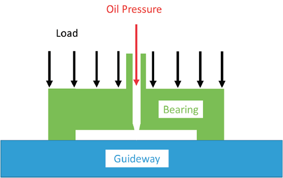
Figure 1. A hydrostatic bearing with insufficient pressure to lift the load.
Figure 1 illustrates a bearing supporting a table. The bearing body (green) has a pocket between it and the nonmoving guide way (blue). At the moment shown, the oil pressure (red) is not enough to support the load (black), and the bearing and the table are in contact. As the pressure is increased, the force between the two components (oil pressure × pocket area) also increases.
When the pressure is great enough to overcome the load, the bearing lifts off the guide way and a small amount of oil begins to flow from the pocket out through the small gap between the bearing and the guide (Figure 2 below). Because the thin film of oil in the small gap prevents mechanical contact, the only force opposing sliding motion between the bearing and the guide way is fluid friction. This low-friction condition is maintained as long as oil flows.
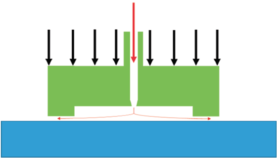
Figure 2. A hydrostatic bearing with a thin oil film separating the moving elements.
This means that in hydrostatic bearings, unlike rolling-element bearings, energy is consumed even at rest because the pump must supply pressurized oil to the cavity. The pump and the flow of oil through the restriction generate heat that must be dissipated. Additionally, the oil must be collected, filtered and recirculated. Care must be taken to avoid contaminating the oil with chips, dirt, water or other debris.
Maintaining the fluid film is easy if the speed of motion is low. If the pressure in the pocket gets too large, the bearing lifts, the gap size increases and more oil flows out of the pocket, reducing the pressure. If the pressure in the pocket is too low, the small gap closes, the oil flow decreases, and the pressure in the pocket increases. In this way, the hydrostatic bearing is self-regulating.
The speed of motion matters, because if the speed is too high, oil from one side is dragged by friction back into the pocket (a hydrodynamic effect), and that side of the bearing becomes starved for oil. This allows contact with the guide way and a sudden increase in the friction force, which damages the bearing or guide way.
A hydrostatic bearing has a large load capacity. The load the bearing can support for a given oil pressure is proportional to the area of the bearing, and hydrostatic bearings carry loads weighing many tons. The bearing provides high viscous damping, which is generated by the oil film. Thicker oil will create more damping, but it will be more prone to suffer from the hydrodynamic problem. The range of motion is limited only by the design of a guide way, including the lengths of its track, hoses and cover, and the ability to fabricate it.
In Figure 2, the bearing is stiff when the load is applied toward the guide way, but not as stiff when the force acts to separate the bearing. For this reason, hydrostatic bearings are often designed in pairs to provide bidirectional stiffness.
Hydrostatic bearings come in many shapes and configurations and can support rotating spindles and linear slides. The oil channels are often machined into the components to reduce the complexity of the supply and drain hoses. Hydrostatic bearings average the small random geometric errors in sliding surfaces, and their repeatability primarily depends on the stability of the fluid supply system. CTE
About the Author: Dr. Scott Smith is a professor and chair of the Department of Mechanical Engineering at the William States Lee College of Engineering, University of North Carolina at Charlotte, specializing in machine tool structural dynamics. Contact him via e-mail at kssmith@uncc.edu.
Related




Subscribers can use MFGAxis notes, saves and discussion tools with their innoNET account.


