



Illuminating inspection
The Look Ahead column features an economical "structured-light" scanner for inspecting parts.
Noncontact, light-based metrology systems are nothing new. But their price tags can be restrictive for smaller part manufacturers, which often become confused when trying to understand what technology to acquire and how to implement it, according to Tom Scotton, director, model and simulation for Connecticut Center for Advanced Technology Inc. CCAT promotes partnerships between industry, academia and government to create a collaborative framework for addressing economic challenges and increasing competitive advantages.
In addition, when visiting small manufacturers to help them minimize cycle times, CCAT personnel would often notice parts stacked up in the metrology room waiting to be inspected, Scotton explained. “That’s when we realized that allowing them to make parts faster only exacerbates the bottleneck problem in the metrology room,” he said.
Courtesy of CCAT
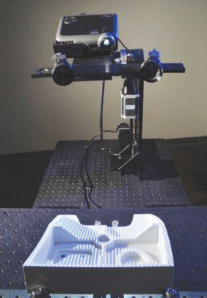
CCAT’s structured-light scanner uses two digital cameras to gather data and a projector to display a series of patterns, typically stripes, onto the object being inspected.
To overcome these issues, CCAT developed, with the company’s Modeling and Simulation Applications Engineer Nasir Mannan as the “technical brains,” an automated quality inspection “structured-light” scanner, Scotton noted. According to Scotton, the scanner is an economical turnkey system that enables a small manufacturer to begin inspecting parts efficiently within a couple of hours after installation instead of the typically long implementation process for a complex, conventional system. The scanner is also suitable for reverse engineering.
He explained that the line-of-sight inspection system uses two off-the-shelf digital cameras to gather data and a high-brightness projector, similar to what might be used for a PowerPoint presentation, to project a series of patterns, typically stripes, onto the object being inspected. From each viewpoint, software automatically converts the series of striped patterns into a 3-D definition of the object’s surface, and then each 3-D viewpoint is aligned and merged into the complete 3-D model of the part. A single- or dual-head turntable axis holding the part indexes that part to capture data from various vantage points. Software algorithms then turn the collected information—the various light patterns—into a 3-D representation of the object for inspection purposes.
Courtesy of CCAT
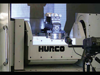
CCAT inspected parts in a Hurco 5-axis milling machine with a wireless communication interface using a structured-light scanner mounted on a tripod with lockable wheels.
In addition to a turntable axis, a machine tool can index the part during the inspection process. CCAT inspected parts in a Hurco 5-axis milling machine at its Advanced Manufacturing Center with a wireless interface using a scanner mounted on a tripod with lockable wheels, Scotton explained.
“We basically machine a part on the Hurco, open the door, roll our scanning head up to the machine and communicate wirelessly with the machine’s controller,” he said, noting the inspection system tells the machine to index the part to various locations. “Then we capture the data and do the inspection [on the machine]. The technology could be applied on a number of different machines.”
Scotton pointed out that the system automatically generates inspection reports, eliminating the potential for human error when documenting measurements.
The system has an accuracy of ±0.0005 ” for inspecting a part that fits in a 5 ” to 6 ” cube, Scotton noted, and system size can be scaled up or down to suit the application. “The question is always going to be what’s the accuracy required by the customer,” he said. “That impacts the cost as well because for better accuracy you have to buy higher resolution cameras.” He noted the system’s price range is from about $15,000 to $70,000.
As of press time, three systems are in place at part manufacturers. Scotton indicated that one of those companies is Oxford Performance Materials, Windsor, Conn., which makes industrial and biomedical parts and biomedical raw materials and is partnering with CCAT to help enhance the technology because “they really fell in love with it.”
For more information, contact Connecticut Center for Advanced Technology Inc., East Hartford, Conn., at (860) 291-8832 or www.ccat.us.
Glossary terms in this article
Related




Subscribers can use MFGAxis notes, saves and discussion tools with their innoNET account.


