

Isolating cutting operations: Turning Performance
The accurate positioning of the cutting tool with respect to the workpiece partly controls the accuracy of a machined part.
The accurate positioning of the cutting tool with respect to the workpiece partly controls the accuracy of a machined part. The tool may not be accurately positioned for a number of reasons, including programming errors, interpolation errors, kinematic errors of the machine tool components or workpiece, thermal deformations, and deflections caused by cutting forces and inertial or gravitational loads. Additionally, machine tools are often positioned near other machines and may be exposed to vibrations transmitted through the supporting floor.
Courtesy of S. Smith
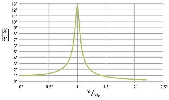
Figure 1. The magnitude of bed motion (X) compared to the magnitude of floor motion (Y) as a function of the floor motion frequency (ω) and the natural frequency of the system (ωn) for a scenario with low damping (c).
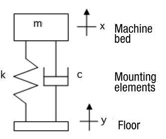
It is possible to design the machine tool bed and the mounting elements, which attach the machine to the floor, to passively isolate the machine. Passive isolation means the transmission of the floor motion to the cutting zone of the machine is naturally minimized without using power or a control system. Figure 2 illustrates a simplified model of the basic principle, in which the machine bed is modeled as a mass that can only move in the vertical direction. It is mounted to the floor through supports represented by a spring and a damper. The floor also moves only in the vertical direction.
The bed motion is indicated by x, the floor motion by y, the bed mass by m, the damping (like a shock absorber) of the mounting element by c, and the stiffness (like a spring) of the mounting element by k. The equation that relates the motion of the bed to the floor is:

Mathematically, this is a linear, second-order, differential equation with constant coefficients. The x and y without dots indicate displacements of the coordinates, the two dots indicate acceleration and the single dots indicate velocities. This equation can be rearranged as:

The left-hand side of the equation looks like a single-degree-of-freedom system, and the right-hand side is the excitation caused by the motion of the base. As with other vibration problems, this equation has a solution that depends on the excitation frequency. That is, the size of the bed motion compared to the size of the floor motion depends on the motion frequency of the floor compared to the natural frequency of the system. The solution to that equation is shown in Figure 1.
Review the print ads from this magazine to continue
This quick advertiser review unlocks the rest of the article and keeps the full-screen reader focused on the ads instead of the page chrome.
Advertisers included in this article experience
Print placements connected to this article
list of products, sizes, specs and capabilities at ezburr.com.
E-Z Burr saves you time and money! Our long lasting patented tools
deburr holes in tough materials in just seconds! Tools are available in all metric and fractional sizes from .040” through 2.0” and custom deburring tools can be produced in 2 to 3 weeks. View our complete.
E-Z Burr saves you time and money! Our long lasting patented tools deburr holes in tough materials in just seconds! Tools are available in all metric and fractional sizes from .040” through 2.0” and custom deburring tools can be produced in 2 to 3 weeks. View our complete list of products, sizes, specs and capabilities at ezburr.com. www.ezburr.com 800.783.2877 Plymouth, MI Easy. Fast. Built to Last.
Visit list of products, sizes, specs and capabilities at ezburr.com. View this placement in the issue recordPrint ads from this magazine
deburr holes in tough materials in just seconds! Tools are available in all metric and fractional sizes from .040” through 2.0” and custom deburring tools can be produced in 2 to 3 weeks. View our complete.
E-Z Burr saves you time and money! Our long lasting patented tools deburr holes in tough materials in just seconds! Tools are available in all metric and fractional sizes from .040” through 2.0” and custom deburring tools can be produced in 2 to 3 weeks. View our complete list of products, sizes, specs and capabilities at ezburr.com. www.ezburr.com 800.783.2877 Plymouth, MI Easy. Fast. Built to Last.
Continue reading
January 2013
Courtesy of “Mechanical Vibrations Modeling and Measurement” by Tony Schmitz and S. Smith
Figure 2. Simplified model of a machine tool bed mounted on a vibrating floor.
The vertical axis shows the size of the bed motion divided by the size of the floor motion. The horizontal axis shows the excitation frequency compared to the natural frequency. If the floor vibration is slow (ω = 0), the machine motion follows the floor motion (X/Y = 1). If the floor vibration is faster, the mounting elements may amplify the floor motion, so the machine motion is much larger. The largest motion occurs where the exciting frequency matches the natural frequency. This is called “resonance.”
To make sure the motion of the machine bed is small regardless of the floor motion, the ratio ω/ωn must be as high as possible. In other words, go as far to the right in Figure 1 as possible. The design element to control is the natural frequency of the system (ωn). The equation for the natural frequency is:
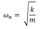
To make the natural frequency as low as possible, the bed mass should be very large, and the springs should be very soft. Because of this, big machine tools often sit on soft mounting pads.
High-precision machines, such as machines for turning with single-crystal diamond tools or wafer polishing machines, need extreme isolation from floor motions. In those cases, the stiff, massive bed may be made of a large block of granite, and would sit on cushions created using low-pressure air in cylinders. Machine tools are, of course, much more complicated than the simple model presented, but the principle of passive vibration isolation is broadly applicable. CTE
 About the Author: Dr. Scott Smith is a professor and chair of the Department of Mechanical Engineering at the William States Lee College of Engineering, University of North Carolina at Charlotte, specializing in machine tool structural dynamics. Contact him via e-mail at kssmith@uncc.edu.
Glossary terms in this article
Related




Subscribers can use MFGAxis notes, saves and discussion tools with their innoNET account.


