



Lessons learned from threading nuts, bolts for gas turbines
Spindle bolts are made from difficult-to-machine, high-strength superalloys. They have very tight dimensional tolerances, which makes thread cutting a challenge. As a result of facing several thread-cutting problems during process development, we have learned important lessons at Mitsubishi.
Gas turbines propel planes and helicopters, tanks, ships and locomotives. The largest turbines can be found in natural-gas power plants that produce electricity for homes and businesses.
At the heart of a gas turbine is a rotor with hundreds of individual airfoils called blades. Blades are arranged circumferentially around a disc, and several discs are stacked together to make a single rotor. Discs are held in place with special bolts and nuts.
At Mitsubishi Hitachi Power Systems Americas Inc., we refer to the hardware as spindle bolts and spindle nuts. These nuts and bolts exert enormous forces on the discs and must last for hundreds of thousands of hours in extremely harsh environments. Therefore, thread quality is critical to the life of both the spindle hardware and the gas turbine rotors.
Spindle bolts are made from difficult-to-machine, high-strength superalloys. They have very tight dimensional tolerances, which makes thread cutting a challenge. As a result of facing several thread-cutting problems during process development, we have learned important lessons at Mitsubishi.
Multiple Configurations
Threads are made in many configurations, typically to a recognized specification like the Unified National. UN and other standards dictate the size and shape of internal and external threads. Engineers usually reference a standard in their designs, but it is not unheard of to be asked to manufacture a nonstandard thread, which is the case with spindle bolts.
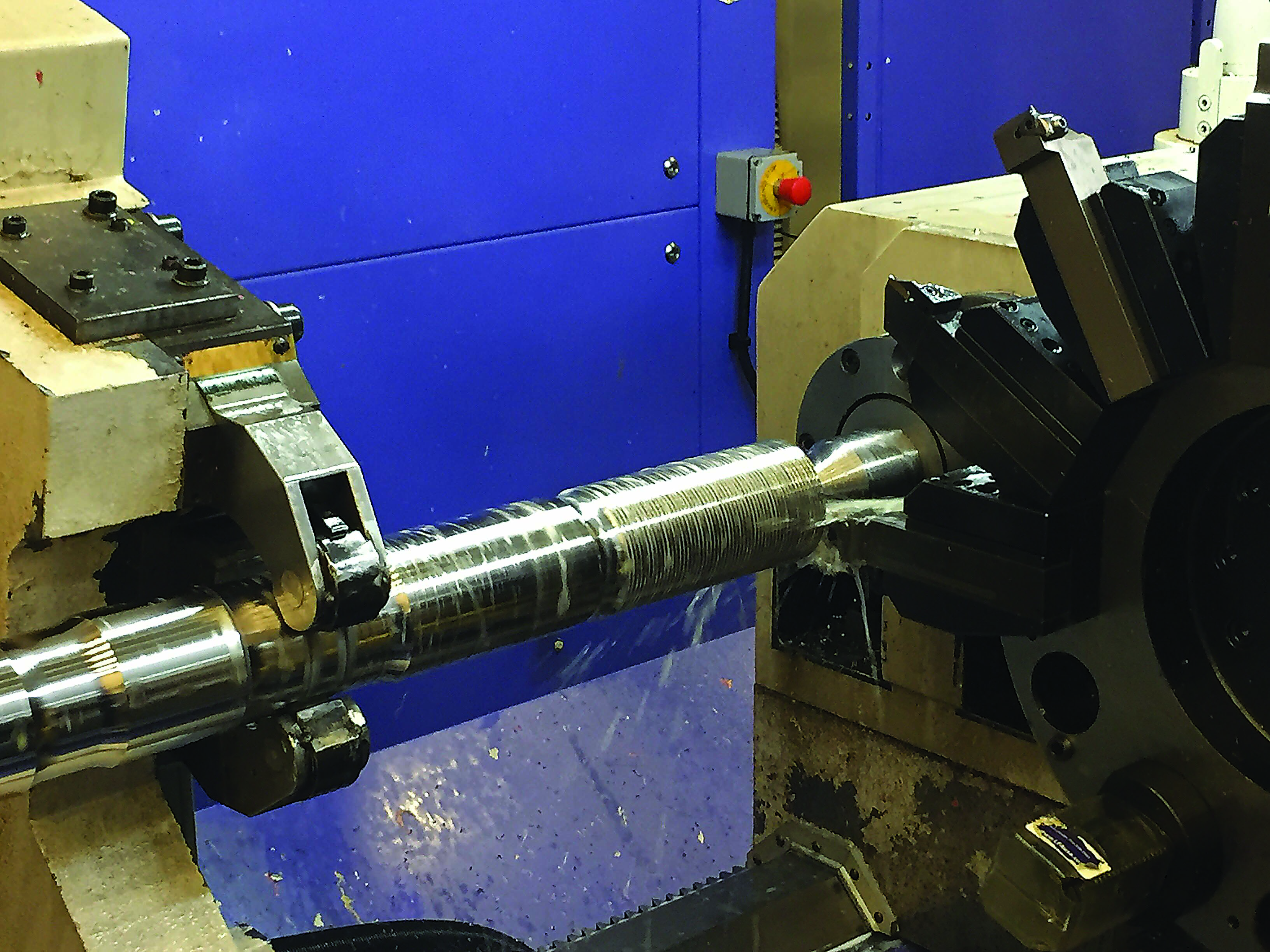
All images courtesy of C. Tate.
UN thread dimensions are given as proportional values based on the pitch or distance between threads. All thread dimensions can be found in a number of reference materials and are not usually provided on the part print. In our situation, we had a UN designation, but the drawing included specific dimensions. Investigation revealed we did not have a UN thread. This prevented us from using a standard thread-cutting tool, because stock tools are made to cut dimensions and geometries given by specifications like the UN standard. Therefore, we were forced to purchase a special carbide threading insert.
After resolving the thread form issue and having the special made, we discovered that our spindle bolt workpiece material was difficult to machine. Initial test cuts produced chatter that could wake the dead. Spindle bolts are long, relative to their diameter. This length makes all machining operations difficult. Because the threads are always cut near a supported area, we decided the tool itself must be producing the chatter.
For any other turning operation, the machinist could adjust the feed rate to put more pressure on the tool to minimize chatter. Because threads require a fixed feed rate to generate the proper pitch, we could not adjust the feed rate. Instead, we lowered the cutting speed. However, when we reached the point where the chatter stopped, the cutting speed was very low and the cycle time was unacceptable. Therefore, changing the cutting speed was not the solution.
Strategic Switch
Success was finally reached when we changed the machining strategy. A CNC lathe allows the programmer to enter the thread-cutting cycle in one of three ways: leading edge only, alternating between leading and trailing edges, or straight in so both leading and trailing edges cut simultaneously.
We had initially arranged the program to cut on the leading edge only, which is the traditional way to set up a lathe for threading. Increasing tool pressure often reduces chatter. However, cutting on the leading edge lowers cutting pressures, thereby causing chatter. We changed the program so the tool would plunge straight in and cut with both sides of the insert. This adjustment increased the pressure enough to eliminate the chatter.
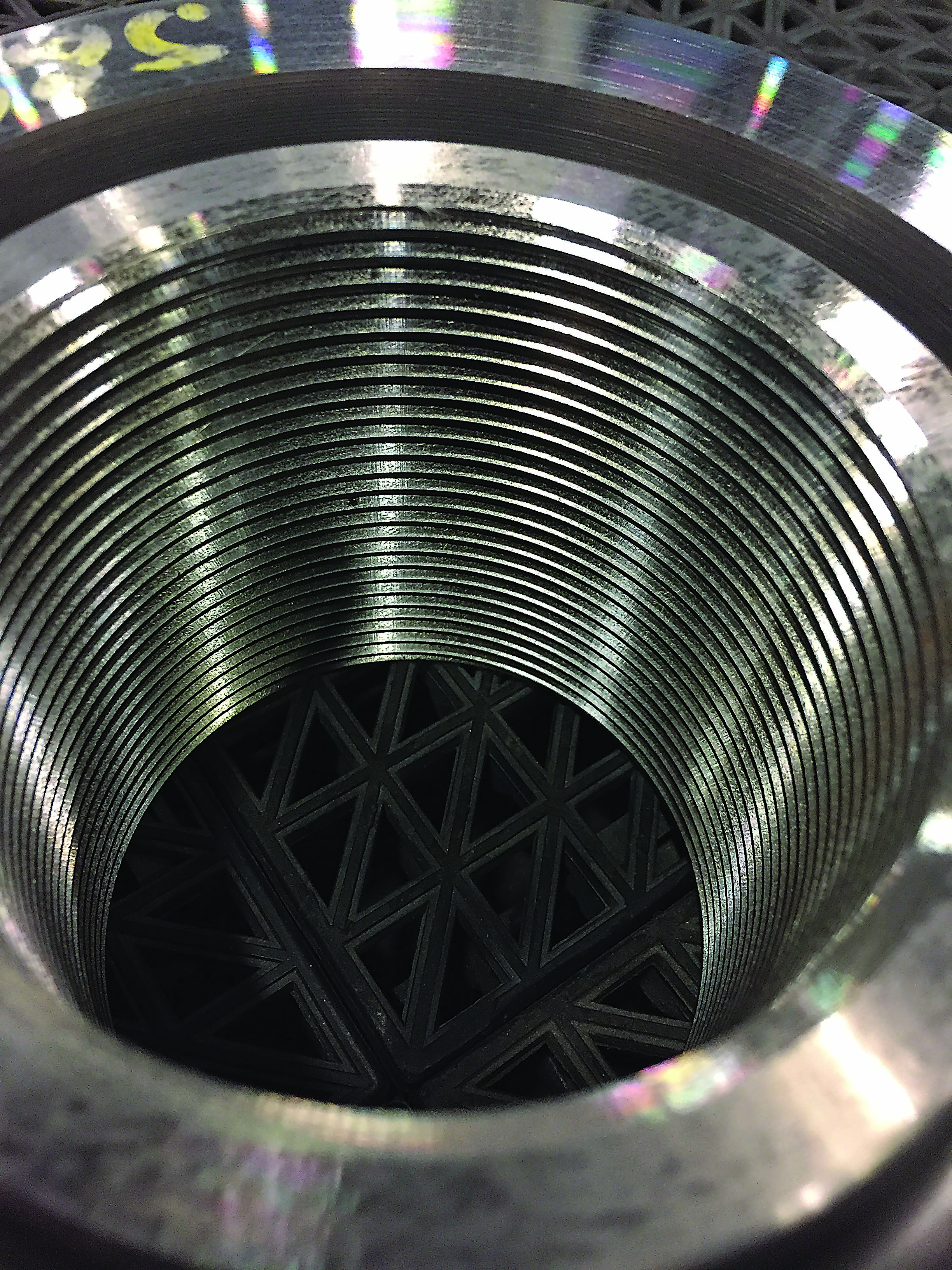
A spindle nut with an odd thread geometry.
After resolving the chatter issue, we found out just how difficult the bolt material was to machine. Our first attempts to cut the threads were dismal; we were unable to complete the threading cycle before insert failure. After investigation, we determined that the cutting speed was too high and, thus, generated too much heat. We also discovered that the coolant was not mixed to the proper concentration. The lack of lubricity resulted in excessive chip welding on the cutting edge, or built-up edge. To overcome these problems, we reduced the cutting speed and increased the coolant concentration. This allowed us to complete the threading cycle.
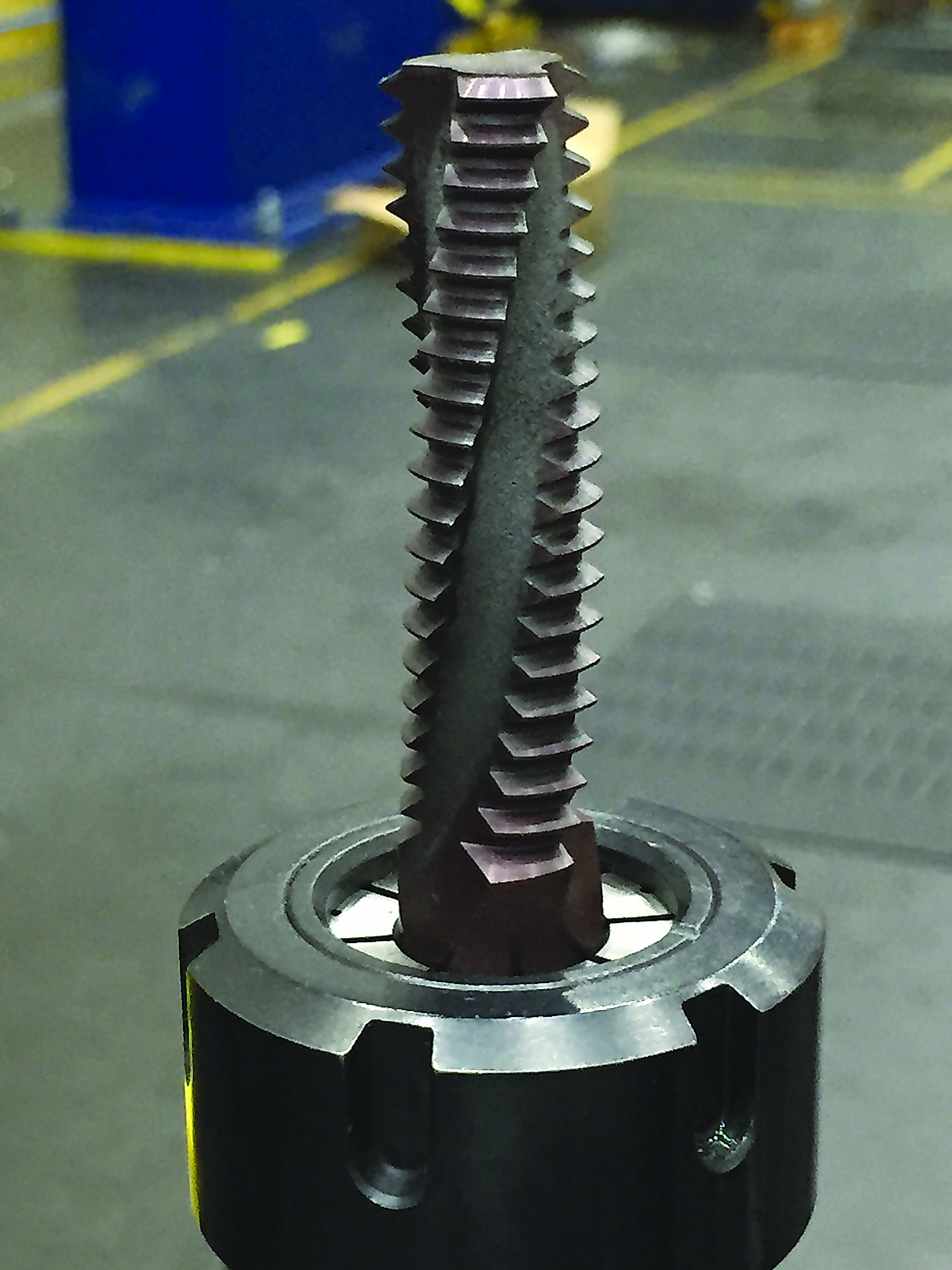
This tool is for thread milling spindle nuts.
Milling Threads
Nuts for the spindle bolts were the next challenge. Nuts are made from material that is much easier to machine, but the thread geometry is difficult to generate. We also had to produce precise start and stop locations for the threads.
Our first attempt to manufacture the nuts was done on a horizontal turning center, which is traditionally used to manufacture these parts. We made a complete set of nuts and installed them in the turbine. However, the start and stop locations of the threads made producing them a painful process.
Going forward with the nuts, we plan on thread milling them, which will provide significant advantages. Thread milling will let us accurately and easily deliver the desired start and stop locations for the threads. In the lathe, we first mark the jaws with a scribe line. We then align the machined features to the line to ensure that the start location for the thread is correct. The machining center allows us to program the start point of the threads, so aligning features will no longer be necessary.
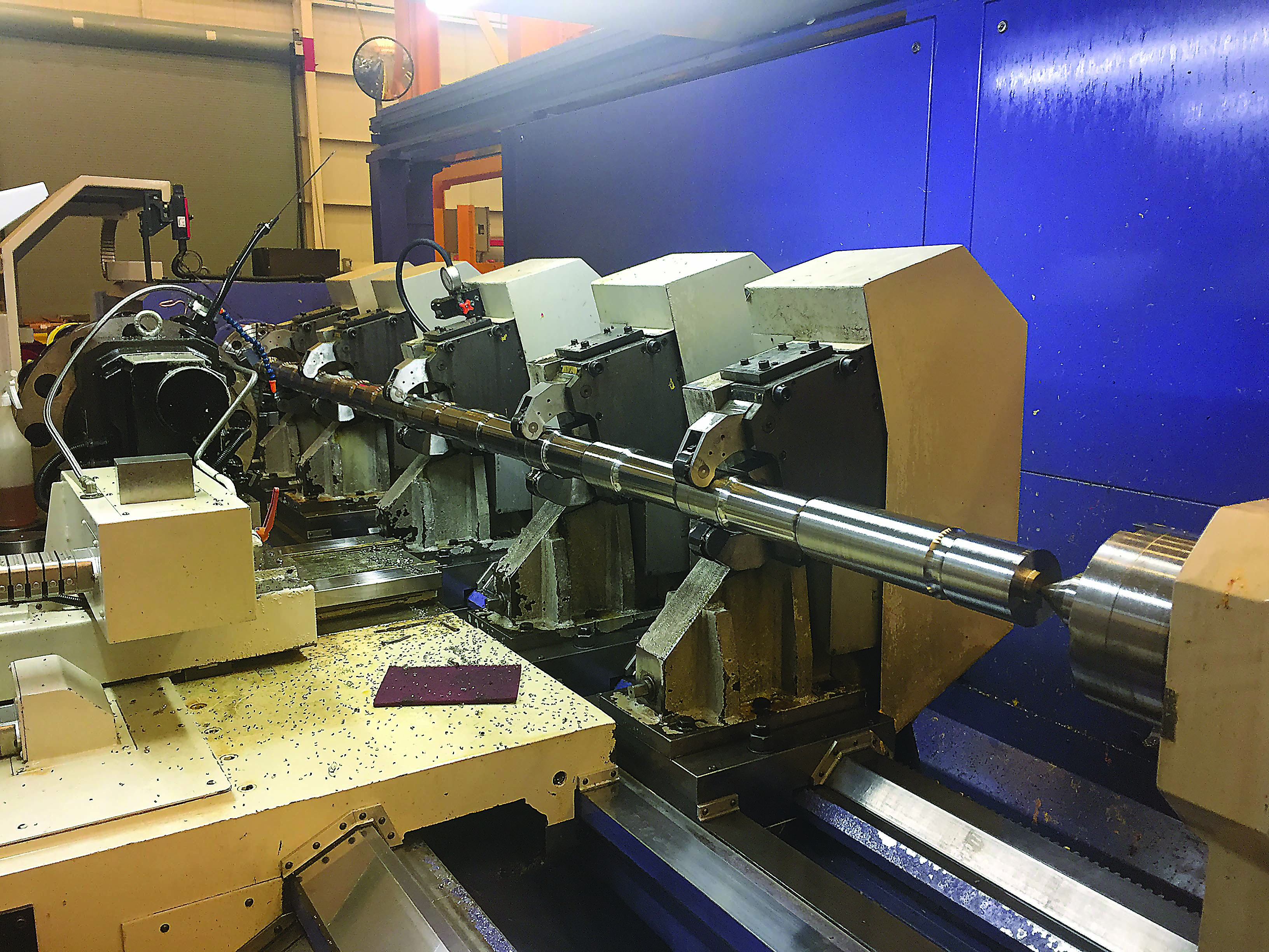
This lathe is used to manufacture Mitsubishi Hitachi’s spindle bolts. Difficult-to-machine alloys and the large length-to-diameter ratio make machining a challenge. All surface finishes are critical, but having a good finish on the threads is particularly so.
Next, we will eliminate the lathe setup. The initial machining process required three setups: twoon the vertical machining center and one on the lathe. Our new process will be done on a horizontal machining center, eliminating the cost of setup on the lathe and reducing the lead time for the part.
The main issue with thread milling is the cost of the tools, which are specials. Fortunately, they should last a long time, and the reduction in setup and lead times should justify the extra cost.
Making threads can frustrate the most-experienced machinists. But threading problems can be overcome with the right information, guidance and some research.
Glossary terms in this article
Related




Subscribers can use MFGAxis notes, saves and discussion tools with their innoNET account.


