Making the most of tired CNC machining centers
Making the most of tired CNC machining centers
While milling has gone high performance, the newest machining centers at your shop were installed when Bill Clinton was president, and the oldest one still uses paper tape. So how might you benefit from emerging high-tech milling strategies?
You've probably heard the news: Milling has gone high performance. You've read the magazine articles about trochoidal milling, watched endless YouTube videos about high-feed and high-speed machining techniques and chatted with your cutting tools salesperson about plunge milling. Unfortunately, the newest machining centers at your shop were installed when Bill Clinton was president, and the oldest one still uses paper tape.
So what difference do these and other high-tech milling strategies make to you?

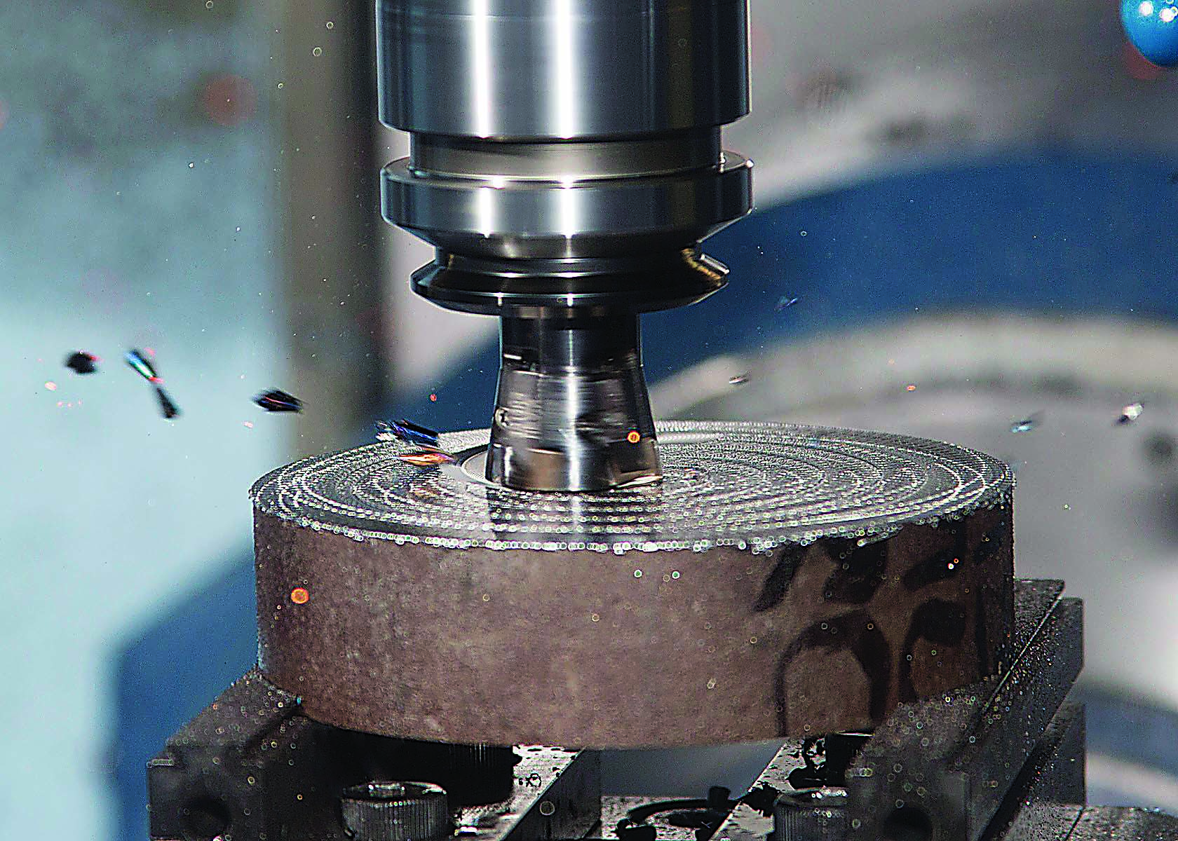
Image courtesy of Greenleaf.
Wouldn't it be cool, though, to toss out those HSS corncob roughers with their 5-ipm (127mm/min.) feed rates and leverage some of these more productive milling methods?
According to Tomas Roman, sales and applications manager for GWS Tool Group, Tavares, Fla., nothing is stopping you
Bye-Bye Corncobs
"We get calls every day from shops that either can't afford or aren't yet ready to buy a new toolchanger. See automatic toolchanger." title="CNC machine tool capable of drilling, reaming, tapping, milling and boring. Normally comes with an automatic toolchanger. See automatic toolchanger." aria-label="Glossary: machining center">machining center but still want to get better performance out of their existing equipment," he said. "Most of the time, it's just a matter of adjusting a high-performance milling strategy to match the capabilities of your machine tool."
One example comes from an aluminum shop in the Dakotas that Roman worked with. A vintage machining center could barely rapid-traverse at the feed rates specified by the CAM system's trochoidal toolpaths, let alone interpolate at those values. Another example is a power generation company machining titanium. The company's older equipment was unable to meet a tool's recommended speeds and feeds.
Despite the apples-and-oranges difference between machining aluminum and titanium, the answer in each case was to increase step-over amounts and reduce feed rates, even though the shop's CAM software didn't agree.

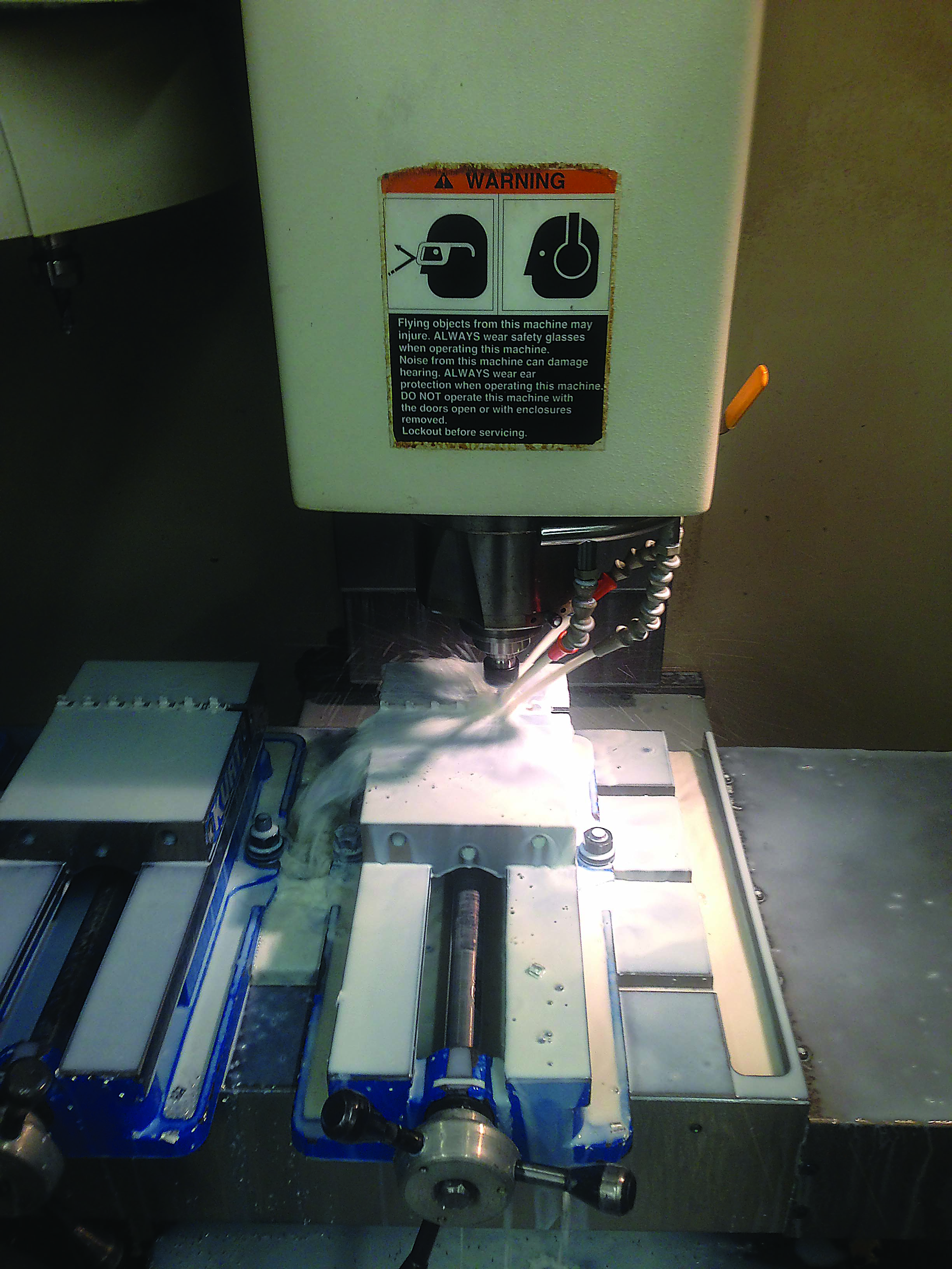
Unless special plumbing is installed, some carousel-style toolchangers can limit cutting fluids to the right side of the spindle, inhibiting chip flow. Image courtesy of GWS Tool Group.
"You can program any job at 500 ipm, but a lot of times the machine can't accelerate and decelerate that quickly, something that's true even on some newer equipment," Roman said. "One indicator that this problem is occurring is when the actual machining cycle takes longer than what the programming software says it should. But by taking a more aggressive step-over and easing back on the feed, we were able to actually increase metal-removal rates compared to the original toolpaths."
However, the less-than-optimal cutting conditions generated greater heat, which caused premature tool wear. The toolmaker countered by adjusting the tool geometry to make the endmills "a little bit beefier." This meant tweaking the relief and rake angles, changing the edge prep to match the application and switching to a more heat-resistant coating.
According to Roman, this beefed-up approach is effective in many "old machine" situations, whether or not a newfangled toolpath is used. That's because the backlash and lack of rigidity common with older CNCs require a cutting tool able to take abuse without complaint.
"Often with poor machining conditions," Roman said, "heat's going to be an issue. Aside from that, tool performance comes down to a delicate balance of aggressiveness and strength, while at the same time applying a carbide grade that's stout enough for less-than-optimal cutting conditions."
Happy With High Feed
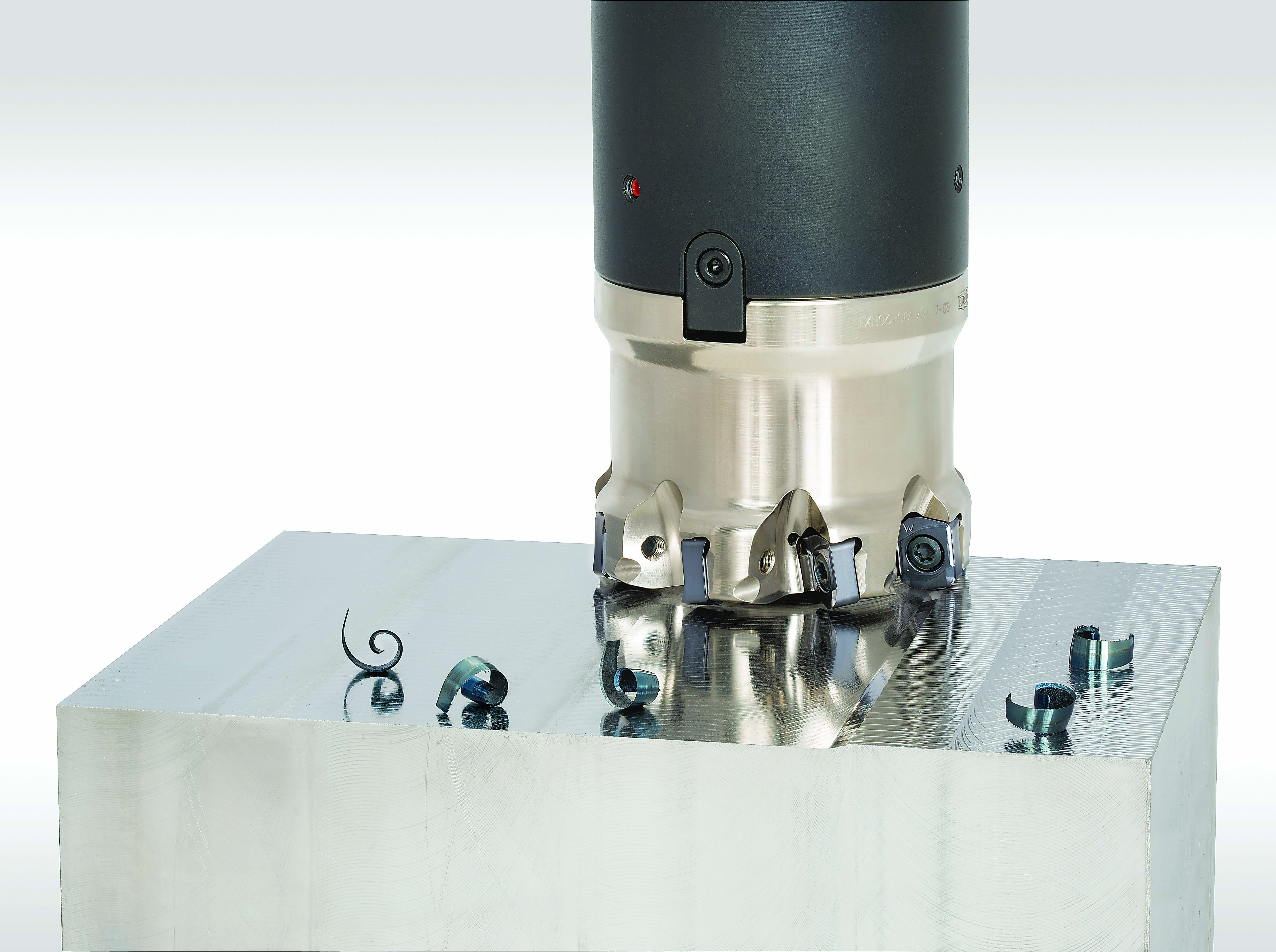
One milling strategy that works especially well on older machines is high-feed milling. Most often, a special resembling a flattened ballnose endmill is applied with a shallow Z-axis, or axial, DOC, relatively heavy radial engagement (upward of 50 percent) and high feed rates, all of which tend to thin the chip while directing cutting forces into the spindle. Roman said one customer was able to replace seven separate tools with a pair of high-feed milling cutters, reducing cycle time and tool costs alike.
Vic Dodd, rotating-product manager for Tungaloy America Inc., Arlington Heights, Ill., saw similar results from his own days in the shop. "I once had a couple of 1997 Bridgeports that I used for mold work and had great results with high-feed tools," he said, adding that with older equipment like that, the spindle isn't strong and the servomotors are weaker than those found on newer machines. "The programmers need to understand those limitations if they're to utilize what's available."

Indexable high-feed milling cutters are an effective machining method for old and new machines alike. Image courtesy of Tungaloy America.
Another limitation that many might recognize is coolant flow. With many older machining centers, Dodd explained, the horizontal, carousel-style toolchanger sits on the left side, a configuration that places the coolant lines on the right side of the spindle. "The problem here is that when you're climb milling on the back of the part, the coolant is forcing the chips back into the cutter. That causes nothing but problems."
Blast Away
There are two ways around this obstacle: Adjust the toolpath accordingly or turn off the coolant and apply an air blast. According to Dodd, the latter should be used by anyone cutting carbon steel, most tool steel and even some stainless steel. "Everybody wants to stick coolant on everything. It's not really an advantage anymore in today's modern machining. About the only time it is needed is when you're drilling and tapping."
That observation holds true for old and new machines alike. The only difference is that many newer machines are plumbed for through-spindle air or have an external air blast already wired in.
Dodd offered another recommendation that has little to do with machine age: Replace toolholders regularly. "I see so many shops that use worn-out toolholders, not realizing that they're not only hurting productivity, they're damaging the machine spindle as well."
Dodd said the same can be said for the Belleville washers and the clamping fingers inside the tool-change mechanism. "People keep running them long after they've worn out. Eventually, something breaks and they end up causing a lot of damage."
The best way to avoid this situation is with proper machine maintenance, a practice that can keep even a
decades-old machine productive. In the meantime, Dodd recommends replacing toolholders and retention knobs at the first sign of wear.
New Chuck, Old Machine
Dodd also suggested tossing out the side-lock endmill mentality in favor of high-performance milling chucks, hydraulic holders and shrink-fit holders, even when used on machines built before any of those toolholding technologies were developed.

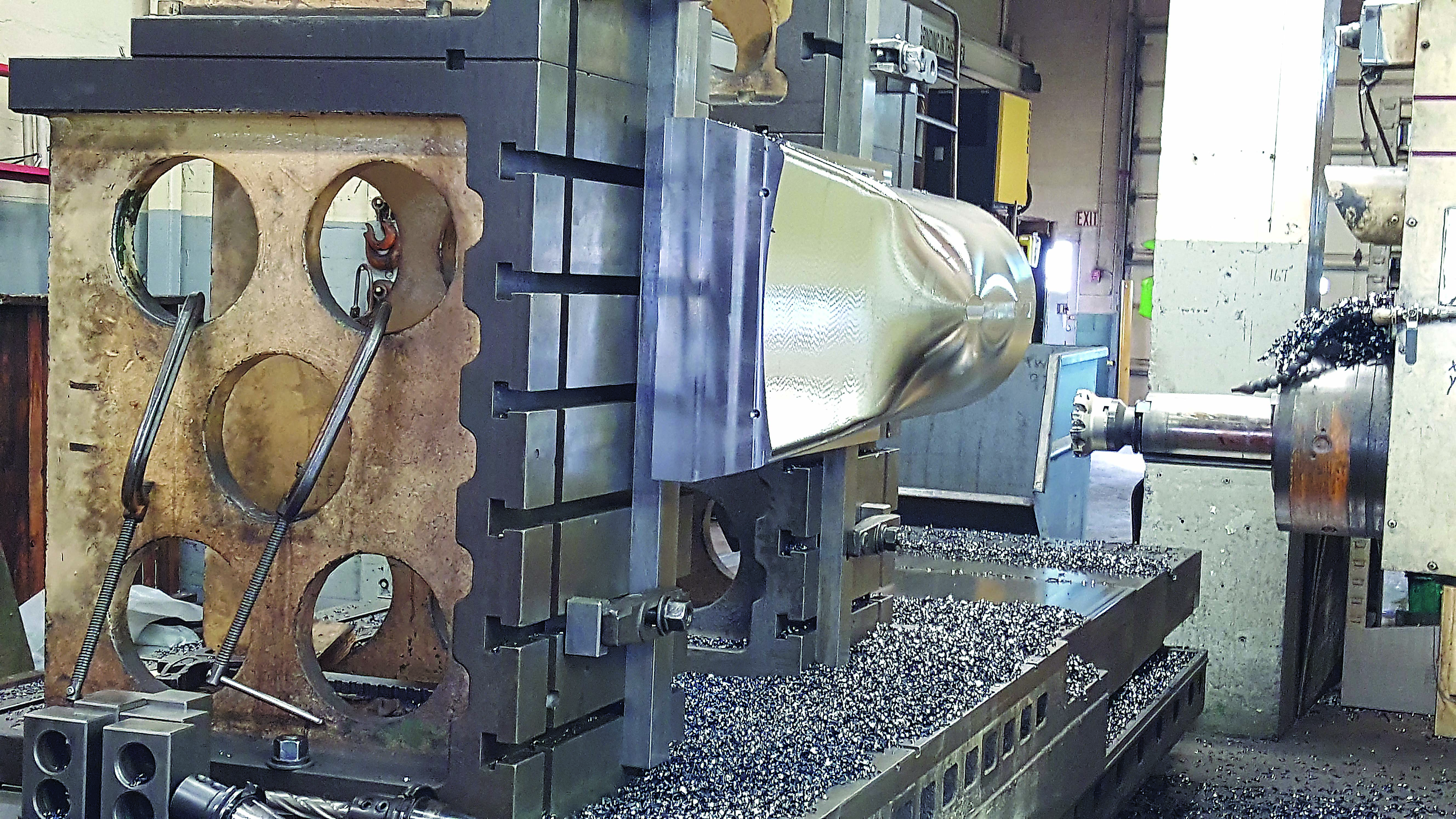
A high-feed milling strategy is used to machine a 4140 alloy steel mold base on a legacy horizontal boring mill. Image courtesy of Tungaloy America.
"People consistently fail to realize how much more performance they'll get from their machine tools—regardless of age—when they invest in high-quality tooling," Dodd said.
Jan Andersson, global director of marketing for Greenleaf Corp., Saegertown, Pa., said success with tired machine tools—or any equipment, for that matter—is about understanding a machine's limitations. "If you look at the industry in general, cutting tool recommendations are designed for average conditions on newer machines," he said. "The problem is that, as machines get older, you begin to lose stability and accuracy."
Andersson added that, at the same time, new machines with faster spindles and higher feed capabilities than vintage ones are being made, widening the gap. "This means that shops must adjust their machining strategies to match the machine tool, not just the application, and suppliers must support them in this effort."
Embracing the Old-Timers
Shops should not avoid modern cutting tools or programming techniques. Instead, they should learn how to make the new and the old coexist. As painful as it may seem, unique CNC programs that respect a machine's advanced age must be generated, resulting in multiple versions for jobs that bounce around a shop. This approach requires moderate cutting parameters that compensate for any specific infirmities, as well as cutting tools able to withstand greater heat and shock and less-than-ideal machining conditions.
As with the others interviewed for this story, Andersson said it's important to stay current on machining technology, even if you can't stay current on machine tools. "For example, people with older machines often discount ceramic as a cutting tool material because they don't have the high spindle speeds needed to reach the correct operating parameters."
New materials have been developed that accommodate a much broader speed range and provide far greater performance than carbide. "That's just one example where the industry has recognized that not every shop has new equipment and has taken steps to meet that need," Andersson said. "It opens up a lot of opportunities for those with older, less-capable machine tools."


