

Managing heat in spindle bearings
Unconstrained, rigid physical objects have six degrees of freedom, or six independent directions of possible motion. There is translation in each of three perpendicular linear directions (X, Y and Z) and rotation about each of those directions. In an airplane, that would correspond to pitch, yaw and roll.
Unconstrained, rigid physical objects have six degrees of freedom, or six independent directions of possible motion. There is translation in each of three perpendicular linear directions (X, Y and Z) and rotation about each of those directions. In an airplane, that would correspond to pitch, yaw and roll.
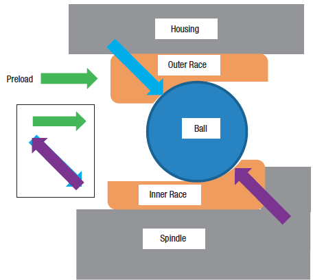
A machine tool spindle is relatively rigid and supported in a fixed housing by spindle bearings. The bearings are intended to constrain five of the six degrees of freedom, allowing rotation of the spindle around its long axis (the Z-axis by convention). Figure 1 shows a schematic cross-section of one side of an angular-contact ball bearing supporting a spindle.
All images courtesy S. Smith
Figure 1. An angular-contact ball bearing without spindle rotation and the contact forces shown as arrows.
In this case, the inner race of the bearing sits against a solid shoulder on the spindle, and a preload is applied as indicated by the green arrow. If the bearing components were absolutely rigid, each of the balls would make contact with the outer race on one point and the inner race on one point. But because the balls and the races are not absolutely rigid, each contact point is spread over a small area.
The preload keeps the balls in contact with both races and stiffens the support by compressing the balls, which act as springs that become stiffer as they are squeezed. In some spindles, the preload is applied by tightening a nut (fixed preload), and, in others, it is applied by a spring or pneumatic pressure (constant preload). Constant preload designs keep the preload more constant even if the spindle expands due to temperature increases.
When the spindle is not rotating or rotating at a slow speed (Figure 1), the preload force is the horizontal component of the contact forces shown by the blue and purple arrows.
The contact forces are larger than the preload force because the races act like wedges. The contact forces on the inner and outer races are equal in size and point in opposite directions, as shown in the small diagram to the left in Figure 1. In this case, the ball rolls on both races and spins about an axis perpendicular to the contact forces.
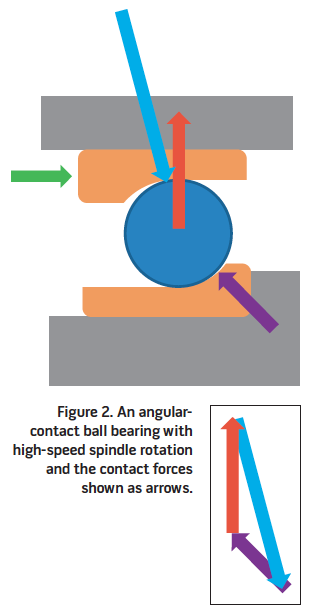
As the spindle begins to rotate (Figure 2), other forces appear, including the centrifugal force indicated by the red arrow. The balls have mass, and, as they rotate around the spindle axis, a force (F) appears that is equal to the mass of the ball (m) times the distance from the spindle axis (r) times the rotational speed of the ball around the spindle axis (ω) squared.
Review the print ads from this magazine to continue
This quick advertiser review unlocks the rest of the article and keeps the full-screen reader focused on the ads instead of the page chrome.
Advertisers included in this article experience
Print placements connected to this article
Kyocera’s M-Series
The latest members of
Milling Cutter Arsenal The M-Four and M-Six Milling Cutters featuring double-sided, thick edge inserts and long lasting MEGACOAT NANO Grades for superior performance t oug h pre c ise unchallenged Experience the M-Series Difference The M-Four and M-Six Milling Cutters are now available as part of the Kyocera Milling Kit Sale
The latest members of Kyocera’s M-Series Milling Cutter Arsenal The M-Four and M-Six Milling Cutters featuring double-sided, thick edge inserts and long lasting MEGACOAT NANO Grades for superior performance
Visit Kyocera’s M-Series View this placement in the issue recordPrint ads from this magazine
Milling Cutter Arsenal The M-Four and M-Six Milling Cutters featuring double-sided, thick edge inserts and long lasting MEGACOAT NANO Grades for superior performance t oug h pre c ise unchallenged Experience the M-Series Difference The M-Four and M-Six Milling Cutters are now available as part of the Kyocera Milling Kit Sale
The latest members of Kyocera’s M-Series Milling Cutter Arsenal The M-Four and M-Six Milling Cutters featuring double-sided, thick edge inserts and long lasting MEGACOAT NANO Grades for superior performance
Continue reading
June 2013
F = mrω2
The rotational speed of the ball around the spindle axis depends on the bearing diameter and number of rolling elements, but it is less than the spindle speed because the ball is rolling. Nevertheless, because the centrifugal force depends on the square of that rotational speed, it significantly increases as the spindle speed increases.
The contact point on the outer race moves, and the size of the contact force on the outer race increases to balance the increasing centrifugal force. The contact forces are no longer equal, but the contact forces and the centrifugal force are in balance (Figure 2). The small boxed diagram shows the vector sum of the forces acting on the ball. In other words, the arrows point along the line of action of the forces, and the lengths of the arrows show the size of the forces. If the forces add up to 0, then the arrows “close” back to the start when they are connected tip to tail.
The contact conditions are sensitive to the precise geometry of the races and balls, the preload applied and the rotational speed. The ball usually rolls on one race and skids on the other, generating a significant amount of heat through friction.
Additional heat comes from the compression and release of the balls as they rotate and from the spindle motor. As a result, managing the heat in a spindle is a major challenge for spindle designers, especially in high-speed spindles.
Lubricating the bearing helps manage the heat—up to a point. The lubrication reduces friction and can absorb some of the heat and carry it away from the bearing. However, too much oil in the bearing can also generate heat by churning. Some spindle designers supply a minimal quantity of oil, such as a few drops per hour, to provide lubrication and avoid churning. Others supply chilled oil in greater quantity, and at greater expense, to absorb the heat.
One of the major reasons for the development of hybrid bearings, such as steel races with ceramic balls, is to reduce the centrifugal force at high rotational speed. Ceramic balls are stiffer and less dense than steel, but they are brittle and more expensive as well, so they are most commonly used in high-speed applications. CTE
About the Author: Dr. Scott Smith is a professor and chair of the Department of Mechanical Engineering at the William States Lee College of Engineering, University of North Carolina at Charlotte, specializing in machine tool structural dynamics. Contact him via e-mail at kssmith@uncc.edu.
Glossary terms in this article
Related




Subscribers can use MFGAxis notes, saves and discussion tools with their innoNET account.


