



Match the process to the part
There's more than one way to machine a part. The trick is to match the part's complexity and volume requirements with an optimal production process.
There’s more than one way to machine a part. The trick is to match the part’s complexity and volume requirements with an optimal production process. As a leading single-source contract manufacturer, Plouse Precision Manufacturing, Harrisburg, Pa., can choose from a wide range of production alternatives. The company’s capabilities include metal stamping, CNC machining, assembly, fabrication, grinding, wire EDM and welding. Part volumes range from single-digit prototypes to production runs of a few thousand. Such a diversified mix of capabilities and part volumes prompts careful consideration of processes and strategies to maximize accuracy and efficiency.
A good example was an approximately 1½ “×1¼ “×½ ” squared-off, U-shaped aluminum bracket Plouse machined for a medical equipment manufacturer. Lot size was about 300.
The bracket featured milling, drilling and tapping on six sides, which would require a minimum of five fixturings to complete on a horizontal machining center. For significantly higher-volume part runs, the HMC would have been a wise choice, as parts for subsequent operations would be set up while the prior ones ran nonstop.
However, for this relatively small part run, Plouse determined that the most efficient method was to perform the operations in a continual sequence on a multitask lathe. The Mori Seiki NL-2000SY machine chosen for the job has driven tools and, in addition to turning, the machine can mill, drill and tap in both the Z and X axes. The machine’s Y- and C-axis motion capability permits machining of off-axis features, and the option of feeding bar stock through the chuck minimizes load time.
The machine enabled Plouse to write one program, setup once and machine the part complete, eliminating refixturing time and the possibility of setup errors between operations.
Working from a customer-provided print, Plouse drew the part in SolidWorks and programmed it in Mastercam. The workpiece material, 36 “-long bars of 2 “-dia. extruded 6061-T6 round bar stock, was fed into the machine through the chuck about 2 ” at a time. “When most people see the part, they think rectangular bar stock,” said Darryl Smith, the company’s engineering services manager. “But it’s round.”
In the first and only turning operation, Plouse faced and rough-turned the bar’s OD to a diameter of 1.660 “. In the next operation, a ½ “-dia., 3-flute, solid-carbide endmill in a live toolholder approached the chuck in the Z-axis and milled and squared the round bar to 1.580 ” wide × 0.500 ” thick × 1.375 ” long (from the free end to where it attached to the bar stock) at a speed of 3,200 rpm and a 40-ipm feed rate. Smith said the parameters were the maximum possible without generating chatter.
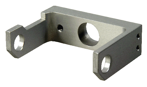
Courtesy of B. Kennedy
Plouse Precision Manufacturing machined this 1½ “×1¼ “×½ ” aluminum bracket for a medical equipment application from a round bar of extruded aluminum.
Next, a 5⁄64 “-dia. HSS drill, applied in the X-axis at 4,500 rpm, made two holes on one side of the part, which then were tapped by a 2-56 UNC-2b thread form tap at 600 rpm. A 0.25 “-dia., solid-carbide endmill, run at 4,500 rpm and an 8-ipm feed, then plunged and interpolated a 0.25 “-dia. hole in the same side of the part. Smith said the endmill diameter could match that of the hole it made because the endmills run undersized. Then the part was rotated 180° and the endmill made an identical hole in the other side.
“On this lathe, it’s like having a 4th axis, because you can index the chuck around and stop it wherever you want,” Smith said. He noted that the tolerance on the two 0.250 “-dia. holes was 0.002 ” to 0.000 ” and “if we were to drill them, we would also have to ream them. Whereas we just dropped in with an endmill, and it only took a second to buzz around them.”
Next, with a live tool in the Z-axis, a 0.375 “-dia. center-cutting endmill plunged and interpolated a 0.375 “-dia. axial hole in the center of the bracket, running at 2,000 rpm and 5 ipm. A C-axis move enabled a 0.089 “-dia. hole to be drilled beside the 0.375 “-dia. hole, which was tapped with a 4-40 UNC-2b thread.
Next, the central 1.4 “× 1.3 ” pocket of the U shape was milled through with a 0.25 “-dia. endmill run at 4,500 rpm and 23 ipm. The same tool then created chamfers and steps on the part at 5,500 rpm and 30 ipm.
At this point in the process, Smith said, “The opening of the U was still attached to the bar, but we had a finished part machined on the end.” He added that the key difficulty in producing this part on the lathe was determining how to remove the finished part from the slug it was attached to without damaging the part.
Plouse achieved that using a 1.00 “-dia., 0.033 “-thick slitting cutter run at 1,500 rpm. “We just went in and nipped both ends off, and it was a done deal,” Smith said. “It dropped into a parts catcher and was brought out to the operator.” Deburring was the final process.
Total part cycle time was about 6 minutes. “The critical issue in making the part was not that it was so difficult to manufacture, but why we chose to do what we did,” Smith said. CTE
For more information about Plouse Precision Manufacturing, call (888) 473-3606 or visit www.plousemanufacturing.com.
Glossary terms in this article
Related




Subscribers can use MFGAxis notes, saves and discussion tools with their innoNET account.


