Maximum-performance milling outperforms traditional milling by a long shot
Maximum-performance milling outperforms traditional milling by a long shot
Within the last decade, multiple endmilling developments have occurred. These include bold, new cutter designs, extremely tough but wear-resistant carbide grades and toolpaths that reduce mechanical shock to machine tool and cutter alike while reducing cycle times by 50 percent or more and extending tool life.
Within the last decade, multiple endmilling developments have occurred. These include bold, new cutter designs, extremely tough but wear-resistant carbide grades and toolpaths that reduce mechanical shock to machine tool and cutter alike while reducing cycle times by 50 percent or more and extending tool life.
This new paradigm of metal removal makes it possible to successfully machine difficult-to-cut materials such as titanium and Inconel using even light-duty machine tools. Moreover, it can be done by anyone with a solid grasp of a few basic machining principles and a CAM system that generates the necessary toolpaths.


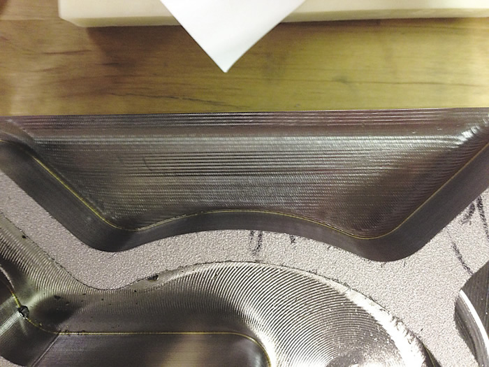
Straight-line peel milling on the edge of a workpiece. All Images courtesy M.A. Ford Manufacturing.

Old School
Before maximum-performance milling (MPM), shops took a more-traditional milling approach. This was not necessarily climb milling or conventional milling—although both play a factor in any milling operation—but rather the type of milling where a cutter is applied at low to moderate feeds and speeds to take heavy cuts, typically engaging 80 percent or more of the tool width and up to 1 diameter deep axially.
This approach can remove a large amount of material per pass, but it often causes minute chipping of the cutting edges, leading to unpredictable results and premature tool failure. The large amount of heat produced by such hogging cuts requires special tool coatings. Endmills require radial rake angles and core thicknesses specifically designed for this type of machining. Specifically, truncated, profile-style roughers, or corncob cutters, are needed to segment chips and reduce deflection during heavy cutting.
On manual equipment, such as manual knee or horizontal mills, this style of old-school milling was performed conventionally, meaning the cutter rotates opposite the direction of feed. This causes rubbing, deflection and heat. With the advent of NC machining centers and their enhanced rigidity, climb milling became possible. As a rule, "climbing" into a workpiece improves tool life and surface finish, but can cause chatter, which generally happens when taking a radial cut that equals 60 to 90 percent of the cutter diameter. This causes the rake face to slap the material rather than curling and severing it, and this technique is hard on the cutter and machine tool.


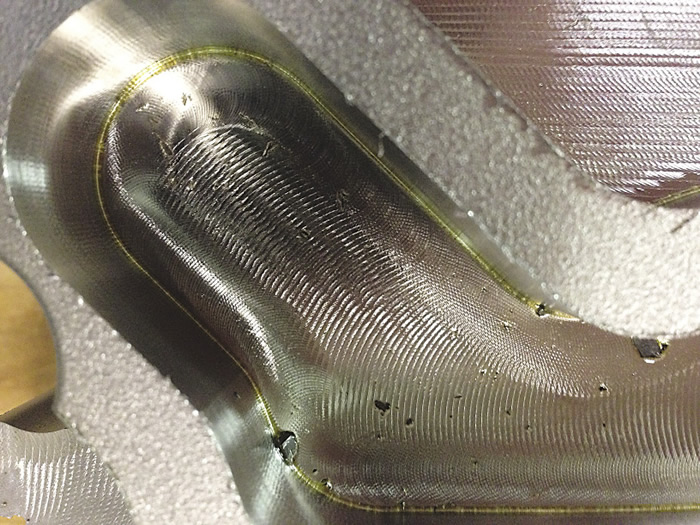
Trochoidal toolpaths are suitable in tight areas, such as slots and small pockets.

Machine builders responded by offering rigid machines with ample horsepower and torque, and duty cycles able to take long, continuous cuts under heavy loads. Machine spindles were likewise improved to endure the constant stresses involved.
Toolholders that eliminate tool pullout caused by high cutting forces were also required, but because machines of that vintage were anything but "high speed," toolholder runout was not the concern it is today.
Peeling Out
Aerospace suppliers were perhaps the first to recognize the need for more-efficient machining processes. By optimizing stock removal and reducing the amount of power required to machine airfoils and other large surfaces, they realized significant energy savings. That optimization came in the form of radically new toolpaths, ones that remove relatively small amounts of material per pass but at much higher feed rates, while maintaining consistent cutter loads to prevent chatter and tool damage.
One of these is straight-line peel milling. It is defined as any toolpath that has a small radial DOC and large axial DOC that travels in a straight line along the inner or outer part of the workpiece. As with all types of peel milling, substantial increases in the feed rate and cutting speed are possible because of chip thinning, the formation of thick-to-thin chips that occurs while climb milling and taking light radial cuts. This reduces heat generation and cutting forces.


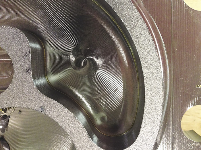
The center of this pocket shows where helical ramping stops and curvilinear spiral peel milling takes over. As the cutter moves into the narrow passage, trochoidal milling begins.

Another is trochoidal peel milling, a type of circular milling that includes simultaneous forward movements. The cutter follows a spiral toolpath to repeatedly remove "slices" of material. Trochoidal, a 2D toolpath, is also used in slot and pocket milling, where space for chip evacuation is limited. In addition, trochoidal peel milling is suitable for cleaning internal part corners, "picking" away at the material left by large roughing cutters.
Curvilinear spiral peel milling, also known as a morphing spiral, is yet another. It is a 2D spiraling cutter path often used in pocket milling. The step-overs are equal as the tool spirals out to complete a part feature. This reduces wasteful acceleration and deceleration by minimizing sharp corners.
For all peel milling methods, endmills with higher-density cutting edges can be applied to increase feed rates and subsequent metal-removal rates.
Mix and Match
Another type of MPM is pocket milling, which requires a starter hole. This hole can be generated with a drill but is more often achieved via a helical ramping routine performed with a center-cutting endmill. Helical ramping is the process of rotating a cutter in a circle up to two times its diameter while simultaneously feeding down in the Z-axis until reaching full axial depth. The circular rotation can be in either direction—clockwise or counterclockwise—which, in turn, enables climb or conventional milling.
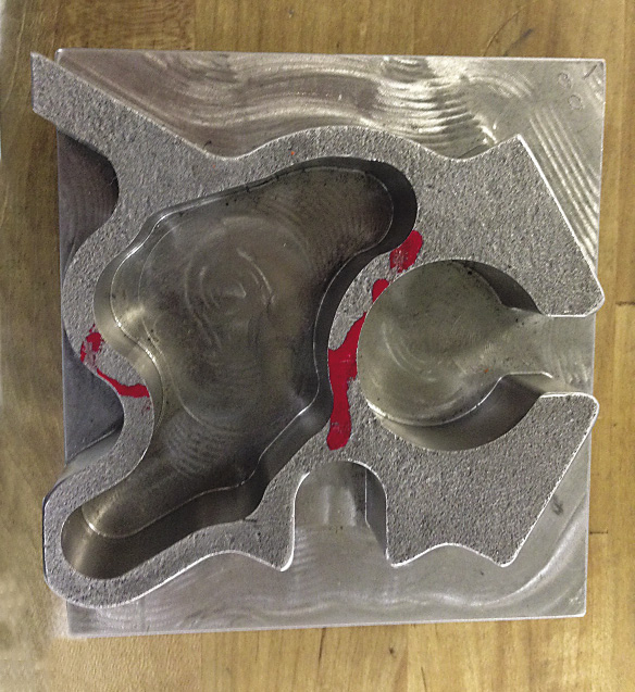
All of these MPM methods might be used in a single part program, depending largely on part geometry, chip clearance and what the CAM system determines is most appropriate for the situation.


This test part uses all of the toolpaths mentioned in the article.

Large-core endmills are appropriate for peel milling, enhancing rigidity and enabling high feed rates. Tool engagement angles and DOC are kept as consistent as possible, and burying cutters in corners is strictly avoided. The resulting toolpath prevents chatter and tool breakage, imparts finer surface finishes, and produces straighter walls and more predictable machining.
Not So Fast
MPM is effective for a multiple materials and applications, but that doesn't mean certain steps aren't required to make it work properly. As mentioned earlier, a good CAM system is a prerequisite. Cycle time reduction is, of course, a primary goal of any CAM system evaluation, but ease of use and reducing programming time are also important. Develop an appropriate test part and criteria, and be sure to check the fruits of your CAM labor by machining the part on your equipment.
Because MPM allows feed rates perhaps dozens of times faster than conventional milling methods, the logical question becomes: Can my machine hack it? Control and servo systems must be fast and accurate enough to avoid overshooting corners or slowing down because of data starvation, such that the feed rate becomes inadequate and tool rubbing occurs.
Depending on the material, spindle speeds of four to five times higher than conventional milling are possible with MPM. When running above 10,000 rpm or so, use well-balanced toolholders. And even though cutting forces are far lighter with MPM, tool pullout is still a concern. Because MPM rips away more material in less time, a shrink-fit, hydraulic chuck or a Safe-Lock-style holder is recommended—no Weldon-shank tools are invited to this party.
You will discover that even tired, old, commodity machines can be turned into metal-eating monsters with MPM. Once all the MPM elements are in place, get to work testing—and documenting—your processes.


