



Measuring machine errors with a ball bar
A telescoping ball bar is a simple, but useful device that provides a quick and inexpensive way to characterize machine tool errors.
A telescoping ball bar is a simple, but useful device that provides a quick and inexpensive way to characterize machine tool errors. The device consists of a telescoping shaft, with precision balls mounted on both ends (Figure 1). The shaft allows the balls to move apart or together along a straight line, but does not allow any other motion. The shaft has a transducer, such as a linear variable-differential transformer (LVDT), which measures the change in length of the telescoping shaft. The fundamental length of the ball bar can be changed by adding nonmoving segments.
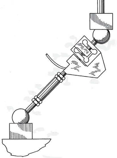
Figure 1. The structure of the telescoping ball bar as described by James Bryan in U.S. Patent No. 4,435,905, which was filed in 1984.
A ball bar is attached to a machine tool using two sockets, which are magnetic and have hemispherical cavities matching the size of the balls machined into one side. One socket is mounted on the machine table, and the other is mounted in the spindle. The spindle and table are brought together, separated by bar length, and the balls are placed in the sockets.
The machine tool is programmed to move in a circle, using two axes, such as X and Y. If the machine tool axes are “perfect,” the motion is truly a circle, and there is no change in bar length or the LVDT reading. If the LVDT reading changes, it provides information about why the motion is not a circle. The LVDT reading is combined with the nominal machine position, and the changes in bar length are shown in an exaggerated scale on a polar plot.
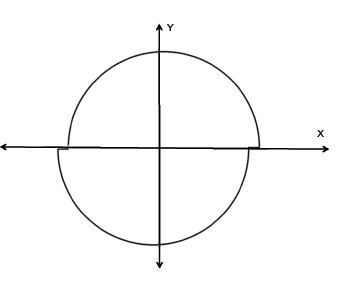
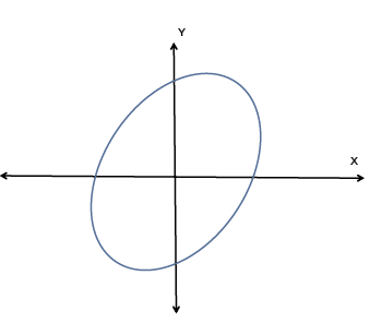
If backlash occurs, as it might with a worn ballscrew or loss of ball nut preload, there is a delay in the portion of the motion where the axis reversal occurs. The resulting plot shows a circle that appears split and shifted (Figure 2). If the moving axes are not square to each other, the ball bar measurement looks like an ellipse (Figure 3). The orientation of the ellipse that results from nonsquareness does not change when the machine is commanded to traverse the circle in a clockwise or counterclockwise direction.
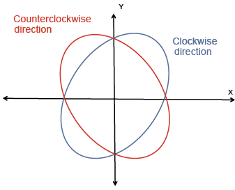
The ball bar measurement also looks like an ellipse if there is a scale error between the axes. But, in that case, the orientation of long axis of the ellipse shifts 90° (Figure 4), depending on whether the circle is traversed in the clockwise or counterclockwise direction.
It is possible to see the characteristic appearances of many other kinds of machine tool errors using a telescoping ball bar, including looseness of gibs, pitch error of the driving screw and stick slip. Of course, the measurement usually includes noise and rarely exhibits only one error. Software is available to help sort the combined measurement into the component errors. These measurements can be repeated using different combinations of axes.
Courtesy of S. Smith
Figure 2. An idealized telescoping ball bar measurement shows backlash.
Courtesy of S. Smith
Figure 3. An idealized telescoping ball bar measurement shows nonsquareness of the axes.
Additionally, although originally intended for measuring quasi-static errors, it is even possible to measure dynamic axis performance with a ball bar. In this case, the circle motion is commanded first at a low feed rate, which depends on the machine, and then at higher and higher feed rates, until the axes can no longer hold the desired tolerance.
The length of travel of the telescoping ball bar in the LVDT configuration is short, but even so, it is possible to measure multiple toolpaths. Essentially, one ball in a socket is the center of a sphere, and the other ball in its socket moves on the surface of the sphere. Generally, any toolpath that lies on that surface can be measured using this device. A circle at the nominal bar length is the largest circle that can be measured. While ball bar measurements are quick and easy, the limited motion makes it unsuitable for measuring full volumetric errors in machine tools.
Courtesy of S. Smith
Figure 4. An idealized telescoping ball bar measurement shows scale error between the axes.
An extension of this device created by Dr. John Ziegert at UNC Charlotte uses a laser interferometer to measure bar length and frees the ball bar from the spherical, short-range constraint. It is possible to repeatedly move the machine along almost any toolpath, placing the base socket in three different positions. The ball bars form the sides of a tetrahedron and allow rapid characterization of the parametric machine tool axes errors (straightness, squareness, pitch, yaw, roll and scale error) over a much larger range. CTE
About the Author: Dr. Scott Smith is a professor and chair of the Department of Mechanical Engineering at the William States Lee College of Engineering, University of North Carolina at Charlotte, specializing in machine tool structural dynamics. Contact him via e-mail at kssmith@uncc.edu.
Related




Subscribers can use MFGAxis notes, saves and discussion tools with their innoNET account.


