



Mimicking machines with simulation
If you're new to 5-axis machining, simulation software can help you efficiently set up a post-processor and verify the strategies coming from the CAM system, according to this month's Get With the Program column.
Costly parts and complex machine tools require a G-code program to be verified prior to pressing a machine’s start button. If you are new to 5-axis machining, whether it’s with a milling or multitask machine, consider obtaining assistance from simulation software to efficiently set up a post-processor and verify the strategies coming directly from the CAM system. If you are already familiar with 5-axis machining, G-code simulation will help reduce noncutting time.
But how can you ensure 3-D simulation generates accurate results to entirely replace the prove-out process usually done on a real machine? The following information should strengthen your confidence.
Courtesy of SPRING Technologies
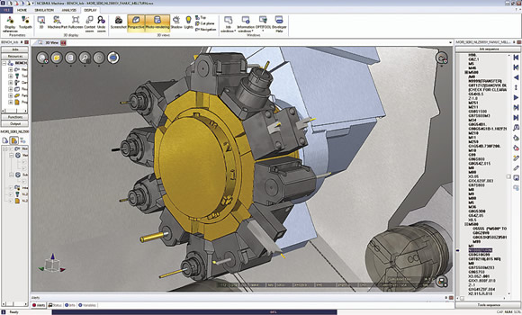
When the space becomes tight, such as on a DMG / Mori Seiki mill/turn machine, simulation software provides critical tooling details.
When done directly on a real machine, the G-code validation process involves three basic steps.
1. Identify program errors. When loading a G-code program for the first time in a machine, the control might provide alarms linked to code integrity. Errors, such as unknown codes, inconsistent motions and out-of-range movements, are identified and require a user to go back and work on the CAM system or post-processor or edit the G code to make it work properly.
2. Check collisions. A dry-run test can consume tedious hours when done directly on the machine. It involves loading the tools in their stations, setting up the fixture and potentially mounting a soft foam-like material as a test workpiece. Some complex programs demand hours of verification with slow motions, but, if executed too quickly, this exercise can cause a dramatic crash. Therefore, it’s risky and potentially expensive. Common errors occur from incorrect program origins, a cutting motion in material with the spindle stopped, insufficient tool length or a rapid motion to reach a tool-change position that generates a tool move across a part and damages it.
3. Inspect the first piece. This part inspection, for example, determines incorrect tool compensations or missing operations.
Ideally, a machine simulation system drives a user through these three steps to replace the actual machine prove-out. NCSIMUL Machine simulation software from SPRING Technologies is based on this three-step concept.
Turning to the machine tool, it is based on two major components: a kinematic model and a numerical control. The kinematic model consists of geometrically connected 3-D models. Most machine tool builders voluntarily provide the models because it’s the most efficient way to ensure the accuracy of the virtual machine.
Simulation software only needs details of the working zone and not the machine’s interior. It’s best to request simplified 3-D machine models from the machine supplier because it accelerates the process of obtaining those models. The virtual kinematic definition will also require some key information, such as the tool-change position and the machine origin, as well as some important values, such as travel limits, maximum feed rates and spindle rotations.
The NC is the decoding logic. Good simulation software directly handles native macros and subroutines uploaded from the real control memory regardless of the complexity of the native macros and subroutines. As an example, NCSIMUL Machine users simply copy the macros and parameter settings from the real machine’s memory and paste them into a Windows folder to access them in the virtual machine.
Today, many cutting tool and fixture providers share their CAD models as well. This allows users to import inserts, tools, toolholders, accessories and fixtures into the simulation environment. Available on their Web sites, usually in STP or STL formats, these models ease simulation implementation. Definitions for tools and fixtures are critical to protect against crashes because they are often moving in a tight working area.
Preparing and testing a part program involves people with different roles in a company. Mainly designed for the programming department, simulation becomes a collaboration tool; the full 3-D environment can now be shared with a customer, machining contractor, corporate group and, even better, shop floor personnel. When using NCSIMUL Machine, for example, operators receive PDF documents containing product and manufacturing information and can review 3-D movies on tablets and other computers with NCSIMUL Player. CTE
About the Author: Silvère Proisy is U.S. general manager for SPRING Technologies, headquartered in France. For more information about the company’s simulation software, call SPRING Technologies Inc., Cambridge, Mass., (617) 401-2197 or visit www.springplm.com.
Glossary terms in this article
Related




Subscribers can use MFGAxis notes, saves and discussion tools with their innoNET account.


