

Nonsmooth move: Drilling Performance
Shops have many choices when texturing—rather than smoothing—part surfaces.
Shops have many choices when texturing—rather than smoothing—part surfaces.
Mirror finishes have long been the gold standard in parts making. But for some applications, smoother does not mean better. Many parts require a specific texture instead.
Textures are applied to part surfaces for several reasons. Some of the most common include:
- Improved aesthetics,
- Reduced friction and wear,
- Increased friction or to provide a specific coefficient of friction,
- Improved oil retention,
- Extended part life,
- Improved adhesion of paint and other finishes,
- Enhanced biological performance,
- Faster bone growth (for orthopedic implants), and
- Development of specific optical and thermal properties.
One notable texturing process is honing automobile engine cylinders. The process produces fine, cross-hatched grooves in cylinders that retain oil as pistons and rings slide by.
Once limited to low-cost, conventional stone honing, engine manufacturers have moved to brush honing and more recently laser honing for some cylinder-head applications. The inner wall of the cylinder head is textured at the upper end, or dead center area, of the piston motion. Textured surfaces prevent the oil film from breaking down during the piston’s short standstill before it moves in the opposite direction. This reduces emissions and fuel and oil consumption.
More Applications
Other examples of textured surfaces are numerous. In machine tool manufacturing, way scraping performs the same function as texturing of engine cylinders—to help retain lubricant and reduce friction and wear.
In hydraulic systems, O-ring surfaces must have circular (textured) tool lines around orifices and mating surfaces. Linear lines allow leakage from the port, whereas circular ones help trap liquid.
On lathes, knurled cylindrical surfaces provide gripping surfaces for manual tightening. In this instance, knurling both produces grooves and raises material above the original surface level to create the texture.
Some indexable inserts have small bumps on the cutting surfaces to decrease chip contact with the insert and reduce rake-face friction. The bumps prevent total surface contact with the chip, allowing the chip to carry most of the heat from machining. This changes the chip compression factor, increasing tool life. In this application, the bumps are pressed in during molding.
Deep-drawn sheet materials, which are produced by being drawn over a male die, often benefit from having minute pockets, called microcraters, on the sheet surface. Produced during the sheet rolling process, microcraters capture the lubricant required for smooth drawing, minimize galling and trap debris from the drawing process. They also provide better surface appearance when sheets are painted.
In orthopedic implants, the texture of surfaces that will come in contact with bone is critical. Most of these surfaces have either roughness for adhesive attachment or porosity to promote bone ingrowth for biological attachment. Texture consistency is crucial, as is the ability to assure freedom from contaminants.
Titanium dental implants that have been textured via blasting with Al2O3, acid etching and concurrent thermal treatment have been found to produce better bone growth than a plain machined surface into the minute crevices of the implant and higher locking strength of the implant in the bone. Healing time can be reduced from 12 to 24 weeks to 6 to 8 weeks when one specific combination of texturing steps is used, according to several dental studies. Tooth implants are often inserted and allowed to heal for several months, but the tooth itself is not added until bone has grown around the implant.
Multiple Methods
Many texturing processes are well known and widely used. Examples include knurling, sanding, brushing, blasting, honing, dimpling and etching. Coining and embossing also create textures. Hammering and rolling are two older processes that mechanically alter a surface. Newer texturing processes involve lasers, electron beams, ion beams and inkjets.
One of the reasons parts manufacturers use texturing is most adhesives work best when applied to etched surfaces, which provide much more area than smooth, or flat, surfaces. The “peaks and valleys” can provide up to 10 times more area than a smooth surface.
Textured metal surfaces encapsulated in epoxy materials also benefit from the extra adhesion that textures provide, which is especially beneficial in epoxy-molded copper parts. Bead blasting is often used to texture these parts. Laser texturing by ablation also provides high-quality adhesion for copper alloy lead frames in mold materials, where the failure mechanism is delamination of the mold compound from the die flag, or leads.
Let’s examine some of the key texturing methods:
Abrasive blasting leaves visible pockets in a surface for holding lubrication. The pockets also reduce contact surface area and provide subsurface residual compressive stresses, which extends service life. Abrasive blasting is probably the most common texturing process, and provides a rapid, low-cost means to improve adhesion of glues, paints and other coatings.
According to Abrasive Blast Systems Inc., Abilene, Kan., blasting is widely used to produce textured surfaces for calendar rolls in paper manufacturing. The metal rolls, which can be up to 20 ‘ long and 5 ‘ in diameter, are blasted to assure tight bonding of subsequent rubber coating. Blasting also removes worn rubber coatings from the rolls during reconditioning.
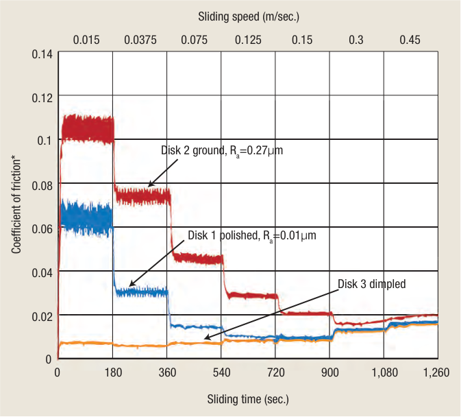
Laser texturing provides a rapid means of producing minute grooves, dimples and other features that trap lubrication for parts such as ring/liner assemblies for engines, mechanical seals and bearings. Use of laser dimpling appears to be growing. Specific diameters and depths of laser dimples provide more than just lubricant reservoirs—they assure proper hydrodynamic film thickness and flow. For some applications, these pockets assure retention of oil films at low sliding speeds, 0.45 m/sec., for example, as one part slides over another on top of oil film. For other applications, they allow faster sliding without galling.
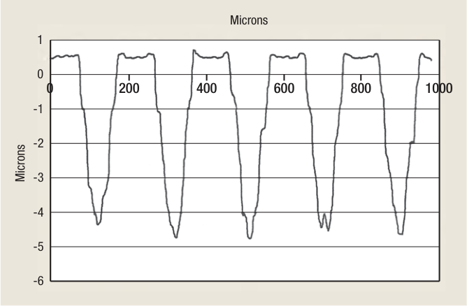
Dimples, including laser dimples, must be deeper than the desired film thickness. For example, the dimple depth must exceed 10µm to assure a 5µm-thick film. For some steel part applications, dimples are 100µm in diameter, 4µm to 5µm deep and spaced at 200µm intervals (Figure 2). A rule of thumb is a cavity surface area of 10 to 40 percent of the planar surface area provides dimple density to assure two to five times better performance than nondimpled surfaces with oil lubricants.
In some instances, improved oil wetting of the surface produces higher sliding speeds because maintaining oil in minute cavities provides hydrodynamic pressure pockets, which reduce friction.
Courtesy of A. Erdemir. Argonne National Laboratory
Figure 1. Frictional performance of ground, highly polished and laser-dimpled steel surfaces in 15W30 oil at room temperature at various sliding velocities. *The coefficient of friction (μ) between two solid surfaces is defined as the ratio of the tangential force (F) required to produce sliding divided by the normal force (N) between the surfaces (μ = F /N).
Figure 1 illustrates the friction coefficients of ground, polished and laser-dimpled steel samples in sliding applications. Figure 2 shows a plane view and a cross-sectional plot of laser-dimpled steel.
A relatively new laser dimpling application uses femtosecond lasers to produce nanoscale and microscale patterns on hard coatings, such as titanium nitride, titanium carbonitride and diamond-like carbon films. Coating life has been increased by factors up to 10, according to G. Dumitru at the Swiss Institute of Applied Physics and other French, Swiss and Russian researchers.
In one study by Swiss and Russian researchers (T.V. Kononenko of Moscow’s General Physics Institute, et al, in “Laser ablation and micropatterning of thin TiN coatings,” Applied Physics A., Vol. 71, 2000, pp. 627-631), laser-dimpled microcraters 3µm to 5µm wide and less than 1µm deep in TiN-coated 440C stainless steel produced 30 percent longer wear life than untextured surfaces. In addition, friction coefficients of textured parts were uniform during the study, compared to many large variations for the untextured surfaces.
Courtesy of Argonne National Laboratory
Figure 2: Plane view and cross-sectional plot of laser-dimpled steel. Chart shows depths of dimples and longitudinal direction (not to scale with depth).
In one application, automotive engine cylinder-head laser dimpling produced 40µm-wide and 8µm-deep pockets spaced 600µm apart to capture oil for lubricating the piston at top dead center. The regular surface surrounding the dimples typically measures 1µm Ra.
TiN is applied to cutting tools to improve hardness and wear resistance. It also lowers friction and provides high thermal resistance and good chemical stability, extending tool life. Drilling studies by Davi Neves and his Brazilian associates, Anselmo Diniz and Milton Fernandes de Lima, show that laser dimpling prior to TiN coating provides an anchoring base that further extends tool life. Laser dimpling 10mm, M2 HSS (62 HRC) drills coated with 2µm-thick TiN had tool life up to 10 times longer than untextured tools when drilling 304 stainless steel. Dimpling, which is present after coating, also reduced cutting forces. The TiN is only 2µm thick and deposits as a uniform layer.
Review the print ads from this magazine to continue
This quick advertiser review unlocks the rest of the article and keeps the full-screen reader focused on the ads instead of the page chrome.
Advertisers included in this article experience
Print placements connected to this article
Visit Toolmex at:
c SMART EXPERTS c INSIDER SAVVY c INDUSTRY EXPERTISE c A PARTNER YOU CAN COUNT ON
For more than 40 years, Toolmex has been your trusted source for the world’s most durable and reliable Workholding and tooling products. And now, we’ve redefined the standard of excellence: we are moving to the next level with Toolmex TMX Chucks for all of your Workholding needs. From manual chucks and power chucks to customized.
c SMART EXPERTS c INSIDER SAVVY c INDUSTRY EXPERTISE c A PARTNER YOU CAN COUNT ON For more than 40 years, Toolmex has been your trusted source for the world’s most durable and reliable Workholding and tooling products. And now, we’ve redefined the standard of excellence: we are moving to the next level with Toolmex TMX Chucks for all of your Workholding needs. From manual chucks and power chucks to customized Workholding solutions, we have a full range of quality products that help you achieve unparalleled productivity with confidence. When you need the right products for the job, turn to Toolmex for simple, reliable, high-value chucks to make your job easier. Visit Toolmex at:
Visit Visit Toolmex at: View this placement in the issue recordPrint ads from this magazine
For more than 40 years, Toolmex has been your trusted source for the world’s most durable and reliable Workholding and tooling products. And now, we’ve redefined the standard of excellence: we are moving to the next level with Toolmex TMX Chucks for all of your Workholding needs. From manual chucks and power chucks to customized.
c SMART EXPERTS c INSIDER SAVVY c INDUSTRY EXPERTISE c A PARTNER YOU CAN COUNT ON For more than 40 years, Toolmex has been your trusted source for the world’s most durable and reliable Workholding and tooling products. And now, we’ve redefined the standard of excellence: we are moving to the next level with Toolmex TMX Chucks for all of your Workholding needs. From manual chucks and power chucks to customized Workholding solutions, we have a full range of quality products that help you achieve unparalleled productivity with confidence. When you need the right products for the job, turn to Toolmex for simple, reliable, high-value chucks to make your job easier. Visit Toolmex at:
Continue reading
August 2010
Dimples are typically produced by ablating the metal surface. A different laser application involves laser-induced chemical etching. The substrate is exposed to a gas, such as a halogen, which spontaneously reacts with the metal to form a solid reaction product layer on the metal. A laser vaporizes the layer, selectively etching the metal. Lasers can also activate some wet chemicals to work faster.
While most texturing processes affect only the topography of a surface, some—like laser texturing—can also provide a new chemistry at the surface and even change the microstructure and composition of the surface and subsurface material.
Inkjet texturing entered the commercial world in 2003 as a result of research at the University of Edinburgh in Scotland. Researchers used equipment originally provided by Intexia Ltd., Peebles, Scotland, to precisely texture bearings and seals, automotive steel and aluminum sheets, embossing rollers and injection mold dies.
Intexia’s high-resolution, drop-on-demand inkjet printer prints a mask onto any flat or cylindrical part surface. A chemical or electrochemical etchant removes material in the nonmasked area, and the mask is then removed in a solvent bath.
The equipment relies on a 126-nozzle inkjet head that dispenses various fluids. Similar equipment is also used for high-speed printing. The concept is straightforward and still applicable, but Intexia disappeared from public view soon after the process was commercialized.
The advantages of this process include its speed and ability to immediately change pattern size and configuration. Compared to laser texturing, inkjet textured surfaces can be much smoother, if desired, and they have no heat-affected zone. This makes inkjet texturing more suitable for thin materials than laser processes.
The Intexia process was developed specifically to produce peaks on the surfaces of mill rolls used to produce cold-rolled automotive sheet steel. As previously mentioned, sheet materials destined for deep drawing benefit greatly by having minute pockets that trap drawing oils, preventing galling and minimizing tearing.
Another inkjet texturing process, developed by Ikonics Inc., Duluth, Minn., is used for etching mold surfaces (see sidebar on page 61).
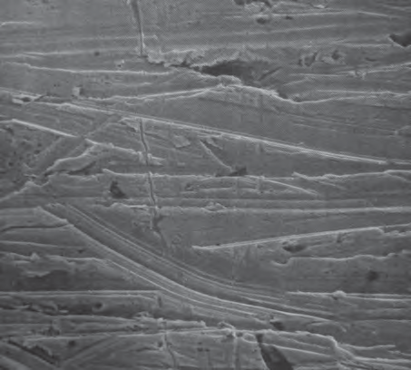
Brush honing has been used for decades to finish automobile cylinders (Figure 3). The process uses abrasive ball-ended brushes such as those manufactured by Brush Research Manufacturing Co. Inc., Los Angeles, to produce a uniform, crosshatched pattern that holds oil better than surfaces produced using other finishing methods, according to several U.S. and Japanese automotive studies. This increases compression and lowers engine wear.
Hot embossing can produce consistent surface features in soft materials. For example, embossing 6061-T6 aluminum at 500˚ C can reproduce 200µm-wide microtextures from a silicon master die. Because it requires elevated temperatures, total cycle times for hot embossing can be higher than those for processes such as laser embossing.
Chemical etching using acid will leave rough textured or controlled polished surfaces, depending upon the application. This low-cost method accommodates large surface areas and continuous production. Portions of surfaces can be masked with sprayed, painted or dipped coatings to prevent etching in those areas.
Courtesy of Brush Research Manufacturing
Figure 3. Results from Flex-Honing ground intake valve stems with 240-grit, boron-carbide tool for 1 minute, shown at 1,000× magnification.
Conventional lithography can also be used on some metals, such as copper. The printed-circuit-board industry is based in large part on lithography after a photomask has been applied to the part to protect key areas. Such applications can also be used on other materials, such as on machined or rolled metal sheet, and are largely dedicated to producing images on parts rather than for functional purposes.
Conventional lithography is also used for some biomedical applications where surfaces must be anchored and free of any contamination. Biological materials (bone, tissue and cells) will adhere to rough-etched surfaces better than smooth ones. Any configuration can be produced in large quantities inexpensively.
In electrochemical texturing, microholes and dimples are made by masking the area for which texturing is not desired and applying chemical or electrochemical action to the exposed areas. This process can produce arrays of microholes.
Microplasma texturing of medical implant surfaces is reportedly a cost-effective alternative to using a titanium-plasma-sprayed porous coating or a hydroxyapatite coating. The process is performed in an aqueous electrolyte by applying pulsed DC voltage to the part, which is typically made from titanium. A microplasma discharge is generated in the thin-steam film between the immersed part and the electrolyte. The process produces a thick oxide layer that can be selectively removed to leave a fine, micro- or nano-scale surface structure.
Studies by the Prokhorov Institute of General Physics, Moscow, have shown that microplasma texturing improves the maximum safe pressure of nickel-chrome joints by four times compared to traditional sand-blasting while decreasing friction losses by more than 1.5 times. Similar results are obtained for other joint materials.
Not all designers are aware of or taking advantage of surface texturing. How about your shop? Can your products benefit from some form of surface texture? Drop us a line about how you see texturing being used. How effective is it in your applications? We will pass on your comments to our readers. CTE
Editor’s Note: For additional information on methods to measure texture, go to the online version of the article at www.ctemag.com. Select “Resources,” then click on “Article Archive.” Under “Date,” search for August 2010, and “Nonsmooth Move” will be one of the articles listed. About the Author: Dr. LaRoux K. Gillespie has a 40-year history with precision part production as an engineer and manager. He is the author of 11 books on deburring and over 220 technical reports and articles on precision machining. He can be e-mailed at laroux1@earthlink.com.
Courtesy of Ikonics
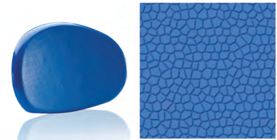
Pattern (right) applied to a mold using the DTX process for making a plastic seat back cover (left). Similar patterns are applied to molds for automotive dashboards and seat covers.
Acid etching goes digital
Ikonics Corp., Duluth, Minn., has developed a digital process for acid etching steel molds. In the Digital Texturing Process (DTX), a DTXJet inkjet-style printer applies an acid-resist fluid on a transfer substrate. The flexible transfer substrate is a coated film developed by Ikonics that accepts the fluid. The self-adhesive transfer film with the printed pattern is applied to the steel mold before it is acid etched. Since it is flexible, the transfer film can follow the contours of the mold, including complex curves, corners, recesses and protrusions. This process reduces the challenge of registration, particularly with multilevel textures, according to the company.
The digital photoresist texturing technology improves acid-etching performance in applications where fine-line definition is challenging using conventional but inherently imprecise wax methods, according to Ikonics. The process can also improve cycle time. Since textured films are produced using digital artwork, files may be altered, edited or reproduced. Files can be digitally stored and encryption-protected.
—CTE Staff
Different ways to measure texture
Most machine shops have standard surface roughness measuring instruments (typically profilometers) for measuring roughness using the Ra scale. While Ra values are useful, other values are better identifiers of consistent textured patterns.
When hydrodynamic lubrication is the goal, researchers have found that Rsk and Rku provide definitive texture measurements. Rsk is the skewness measured by the surface roughness measuring device, and Rku is the kurtosis value of these measurements. Friction is reduced when kurtosis is increased and skewness becomes more negative.
Different manufacturing processes produce different roughnesses, but consistent use of any process tends to produce consistent readings of these two measurements. These values reveal that surfaces with high kurtosis and low skewness show plateau-like surfaces with deep valleys.
For typical values, increasing dimple spacing reduces skewness and increases kurtosis, which lowers friction. For the typical size range of dimples used, increasing dimple diameter will increase skewness and reduce kurtosis, which increases friction.
Scanning electron microscopes can identify texture consistency. They can provide X-, Y- and Z-axis measurements as well as molecular level imaging, if desired. SEM measurements tend not to be as accurate as those from surface-texture measuring devices. Used in combination, however, SEMs and surface-roughness instruments provide users with both the visual and numerical data required to document texture.
The combination of SEM and roughness measuring devices can accommodate a measurement range of 1nm to about 500mm horizontally, and 1nm to 1mm vertically.
—L. Gillespie
Glossary terms in this article
Related



Subscribers can use MFGAxis notes, saves and discussion tools with their innoNET account.


