

Post-processing should not work: Design & Engineering
The creation of a part program for a CNC machine tool usually starts with a part drawing or model that contains the part material, geometry and tolerances.
The creation of a part program for a CNC machine tool usually starts with a part drawing or model that contains the part material, geometry and tolerances. The manufacturing engineer starts with this model and then selects the required cutting tools, designs the fixturing, selects the machining strategy and chooses the toolpaths and machining parameters.
Usually, software assists with the creation of the toolpaths. Canned routines are available to automate much of the labor required for programming common tasks. Pocketing routines exist for many strategies, such as spiral in or spiral out, and other routines exist that favor either climb or conventional milling. Geometry simulation software often verifies that the final geometry is correct and there are no unintended collisions between the tool, holder, fixtures and workpiece.
At this point, the NC program is ready for post-processing. Post-processing is the process by which the NC program is translated into the commands necessary to create the part geometry on a specific machine. Each individual machine has its own piece of software, a “post,” which takes the NC program created by the manufacturing engineer as input and produces the commands expected by the machine tool controller as output. The post is sometimes provided by the machine tool builder, but usually the end user creates the post.
The post is machine-specific because, for example, different machines have the axes arranged in different configurations. Five-axis machines with A and B axes require different commands than machines with A and C axes to achieve the same relative motion between the tool and workpiece. Different machines have different available features (like the ability to execute a loop), expect different header information and differ in their interpretation of nonstandard M and G codes. The post-processor handles all those details.
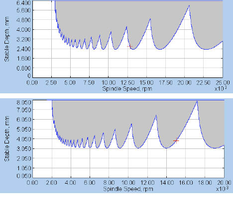
Stability lobe diagrams for the same endmill run in a machine tool with a 25,000-rpm spindle (top) and in a machine tool with a 20,000-rpm spindle (bottom).
Review the print ads from this magazine to continue
This quick advertiser review unlocks the rest of the article and keeps the full-screen reader focused on the ads instead of the page chrome.
Advertisers included in this article experience
Print placements connected to this article
Brubakertool
Tap into
Tap into Contact Brubakertool at 1. 800-522-8665 or visit brubakertool.com.
Visit Brubakertool View this placement in the issue recordPrint ads from this magazine
Tap into Contact Brubakertool at 1. 800-522-8665 or visit brubakertool.com.
Continue reading
August 2009
In principle, the NC part program can be created based only on the geometry of the desired part and without a specific machine in mind. Later, that same part program can be “posted” for one machine or another, depending on machine availability or cost, for example. If all that mattered was the part geometry, tool and machine, then this strategy should work. If the machine and workpiece were infinitely rigid, and the machine had infinite torque and power, then this strategy should work. But it doesn’t work, or at least it shouldn’t work.
That’s because individual machine tools have unique cutting performance characteristics. Their torque and power vary with the spindle speed. They deflect in response to cutting forces, and the cuts they can make are often limited by the onset of chatter.
The stability lobe diagrams on page 21 are for the same endmill run in two similarly sized CNC milling machines. The vertical axes show axial DOC, and the horizontal axes show spindle speed. The shaded areas are cutting conditions that will lead to undesirable chatter, and the white areas represent smooth, stable machining.
If the manufacturing engineer selected 20,000 rpm for the spindle speed and 4mm for the axial DOC, the top-diagram machine would make the part with no problem, while the other machine would experience severe chatter. If the selected spindle speed was 17,500 rpm, and the axial DOC was 5mm, then the lower-diagram machine would make the part with no problem, while the first machine would experience severe chatter. If the manufacturing engineer selected 17,500 rpm for the spindle speed and 1mm for the axial DOC, then both machines could make the part without chatter, but both machines would be severely underused. In an environment where productivity is a key component of manufacturing competitiveness, selecting cutting conditions that optimize machine performance is a clear advantage.
That means NC programs should be written with a specific machine in mind. For any tool the manufacturing engineer wishes to apply, a stability lobe diagram should be created for that tool in that machine. The engineer should select cutting conditions for that tool and machine that maximize machine productivity, while staying safely inside the stable zone. With a specific machine in mind, the cutting conditions can be chosen respecting the machine-specific limits, including torque and power. Otherwise, if an NC program written without specific machine knowledge is post-processed and it works, that is bad. It almost certainly means the NC program was too conservative. CTE
About the Author: Dr. Scott Smith is a professor at the William States Lee College of Engineering, University of North Carolina at Charlotte, specializing in machine tool structural dynamics. Contact him via e-mail at kssmith@uncc.edu.
Related


Subscribers can use MFGAxis notes, saves and discussion tools with their innoNET account.


