



Proper way to measure feature concentricity
In a recent blog post, Joshua Jablons, president of Metal Cutting Corp., Cedar Grove, N.J., discussed a topic that leaves many machinists scratching their heads: What is the proper way to measure feature concentricity on a round workpiece?
In a recent blog post, Joshua Jablons, president of Metal Cutting Corp., Cedar Grove, N.J., discussed a topic that leaves many machinists scratching their heads: What is the proper way to measure feature concentricity on a round workpiece?
This excerpt from the blog does a great job explaining two of the most common geometric dimensioning and tolerancing part callouts:
“As the name implies, GD&T circular runout is typically used to control circular features of a part, such as shoulders, tapers and fillets. Sometimes simply called ‘runout,’ it specifies how much the feature can vary in relationship to a reference point as the part is rotated around an axis—in basic terms, looking at how much ‘wobble’ there is in the feature in relation to the reference point. The circular runout tolerance zone is represented by a two-dimensional area into which all points on the feature’s surface must fall.
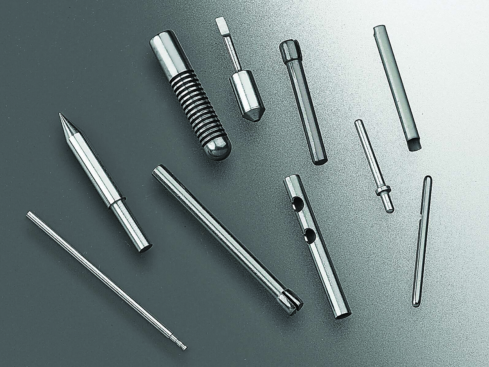
Runout and concentricity on small parts like these are often difficult to check with a CMM or Talyrond, so operators must instead rely on dial indicators and V-blocks. Image courtesy of Metal Cutting.
“GD&T total runout, on the other hand, is used to control variation in all the points on the surface of a rotated part with regard to the part’s rotation on its axis. It is a characteristic that is generally called out when you have a part that must rotate around a central axis and have all points on the entire surface of the part be in spec. The total runout tolerance zone is a three-dimensional, cylindrical area surrounding the reference point, into which all points on the rotating part must fall.”
For shops like Metal Cutting, which specializes in centerless grinding, small-part turning and burr-free abrasive cutoff and polishing of parts for the medical, semiconductor and other industries, spinning the part against a dial indicator is adequate for most total- indicator-runout requirements.
But Jablons said this method might fall short for some shops. Those making parts on a mill-turn machine or machining center, for example, must often measure holes and other cylindrical features against a true position tolerance. In this case, a coordinate measuring machine is probably the best option, although a vision machine or a height gage and dial indicator will do in a pinch. For those machining shafts with critical bearing journals, a Talyrond or similar “circular geometry checker” is frequently the preferred method for measuring roundness and cylindricity relative to a datum.
“How you measure the part is entirely dependent on what you’re making,” Jablons said. “For very small parts like ours, it’s difficult to take it off the machine, put it on a roundness checker and then stick it back in the machine. And a CMM is simply too big for most of what we do.” To achieve excellent part quality, Jablons said the company relies instead on the skill of its machinists, coupled with a good understanding of customers’ requirements.
Glossary terms in this article
Related




Subscribers can use MFGAxis notes, saves and discussion tools with their innoNET account.


