Pros and cons of indexable tools
Pros and cons of indexable tools
The single most significant benefit offered by indexable tools is the ability to renew the cutting edge without having to remove the cutting tool from production.
Cemented-carbide cutting tools have been in use since the late 1920s and are now ubiquitous in the metalcutting world. Around 1950, tools that accept cemented-carbide inserts became common in metalworking and are still considered a basic necessity.
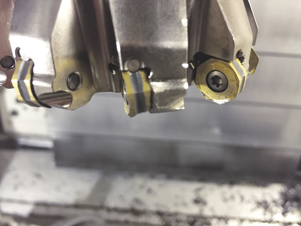
Indexable cutters are typically constructed of a steel body that has machined features, allowing for the accurate positioning of inserts. Steel tool bodies also provide a method for clamping inserts along with a method for attaching the assembled body and inserts into the machine tool.
Benefits Over Solid Tools
Before the proliferation of carbide inserts, it was always necessary to remove solid cutting tools from machines to sharpen them. Tool sharpening was such a significant amount of work that large manufacturers often had grinding departments dedicated to tool sharpening. Therefore, the single most significant benefit offered by indexable tools is the ability to renew the cutting edge without having to remove the cutting tool from production. Renewal of the cutting edge is typically done by unclamping the insert and turning or flipping it (indexing) to a fresh cutting edge or replacing a completely worn insert with a new one.

Solid drills, taps and other types of cutting tools are still used, depending on the application, but the indexable turning tool is the predominant tool of modern turning operations. Indexable tools have effectively displaced HSS, brazed-carbide and custom form tools, which were common prior to the proliferation of CNC machines. An indexable turning tool paired with the multiple-axis motion of a CNC machine tool simplifies the creation of complex shapes, virtually eliminating the need for dedicated turning tools.
In addition, applying indexable drills on a lathe provides some distinct advantages over traditional solid HSS or carbide twist drills. It is common for a programmer to make a hole with an indexable drill and then step off center and cut the hole to a larger diameter, which can eliminate the need for a boring bar. CNC lathe turrets frequently suffer from misalignment because of wear and tear, and misalignment of the machine can damage standard drills. On the other hand, indexable drills are more forgiving than standard drills when used on machines with questionable alignment.
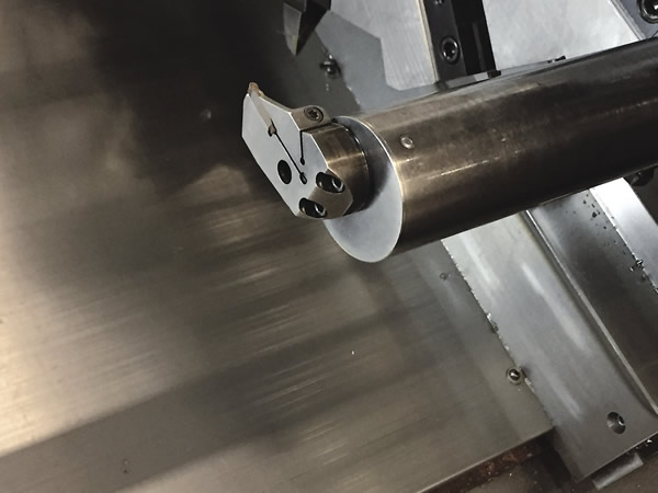
Groove-turn inserts, which have made grooving tools multifunctional, like indexable drills, present a significant development in turning tools. Old grooving technology allowed cutting in only one direction; groove-turn inserts allow the user to make radial as well as axial cuts.
The Common Touch
There is a tremendous amount of commonality among indexable turning tools. Turning inserts are manufactured in common shapes, such as diamond, square and round. The shapes and sizes of these inserts are made to standards governed by bodies such as ANSI and ISO. Their commonality gives the programmer and machinist an almost unlimited selection of insert grades and cutting-edge geometries. All of the major cutting tool manufacturers produce turning inserts to these standards, so finding an insert that gives the best performance is relatively easy.
Unlike turning tools, indexable milling tool bodies tend to require insert shapes and geometries that are not common among manufacturers, forcing users to purchase inserts made specifically for the brand of mill they use. However, toolmakers have been developing and offering families of milling tools that utilize their proprietary shapes across a range of cutter bodies. Having a family of cutter bodies that accept the same insert reduces tool inventory while providing some flexibility to programmers and machinists.
Most of the major toolmakers manufacture custom indexable form tools. Unlike form tools for turning, form tools for milling are still a viable way to complete a complex geometry, especially when a shop is trying to reduce cycle time and cutting tool inventory. Parts with features such as multiple steps, radii and chamfers require the use of multiple tools to create them. The advantages of custom, combination indexable form tools are reduced cycle times, reduced tool inventory and improved part quality.

Unfortunately, custom indexables are expensive and often require modified inserts, making the inserts expensive as well. For these reasons, custom indexable tools are usually reserved for high-production environments or for manufacturing very expensive parts.
A significant indexable milling innovation was the development of plunge milling for roughing large cavities like the ones machined in molds. Tools used to rough deep pockets or shoulders can be quite long. In traditional roughing operations, radial loading of long cutting tools from side-to-side cutting motion induces chatter. Plunge-roughing is done by feeding the tool axially, which directs cutting forces into the spindle taper, where the machine is most rigid. Plunge-roughing results in much higher metal-removal rates when long tools are needed.
On the Other Hand …
Indexable tools do have some drawbacks. Inserts are usually made by pressing carbide powder and binding materials into a die under high pressure. After forming, the inserts are heated to high temperatures and sintered, binding the powder and other materials together and giving the insert its strength. This process results in a cutting edge that is stronger than the edge of a ground cutting tool. Although stronger, the formed cutting edge is also less keen, or sharp, which can limit the ability of the tool to effectively take a shallow DOC, which can make finishing difficult.
Variation in insert pockets and insert size can cause the cutting edges of multiple-insert milling tools to lie in slightly different planes. The result is often less-than-desirable surface finishes or noticeable steps in shoulders. In these instances, the user may be forced to use another type of tool for finishing.
As industry continues to demand modularity, lower inventory levels, higher productivity, increased tool life and universal tooling solutions, indexable cutting tool technology will continue to make advances and replace obsolete cutting tools.

Out with the Cam-out Effect
When tightening or loosening screws with conventional conical profiles, such as the cross-recessed Phillips head, the cam-out effect is a common problem. In accordance with the triangle of forces, some of the energy cams out of the screw, causing the screwdriver or bit to slip out of the screw head. The user has to counteract cam-out by applying additional force.
Profiles with straight sidewalls, like hex, Torx and Torx Plus drive systems, eliminate the cam-out effect. The basic difference between the Torx and the Torx Plus designs is that the former incorporates a 15° drive angle and the latter has an almost 0° angle, which ensures optimal torque load is transmitted to the screw. Although the straight sidewalls of the Torx drive prevent cam-out, its 15° drive angle prevents full engagement of the drive bit and fastener and still permits a small amount of radial stress, which can reduce bit life.

With the hex design, the points of contact cause stress risers to develop. In addition, damage to the screw head is almost inevitable, and the transferable torque is relatively low in comparison with the level of force that has to be applied.
The danger when tightening and loosening screws is the high stress concentration that occurs when turning the fastener. High stress occurs mainly in hex screw heads, which can cause stress in the tool and screw. The elliptically based geometry of the Torx profile and the associated lack of angular edges minimize stress concentration. This, in turn, protects and extends the life of the screw and tool. The elliptically based geometry also provides a small tolerance range between the bit and screw, improving force closure.
The Torx Plus profile further improves the force closure via its working angle of almost 0° and its larger core diameter. This allows a higher torque transfer and prevents the screw and tool from suffering damage.
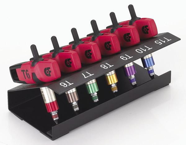
Producers of carbide inserts use the Torx or Torx Plus system to fasten inserts to tool bodies, but the trend is toward Torx Plus because it more efficiently transmits the torque generated by the driver to the screw. With the Torx Plus drive, little or no end load is required to keep the driver engaged in the recess, reducing operator fatigue and muscular stress during manual assembly. As a rule, carbide insert manufacturers prefer hand tightening over power-driven systems.
—Alan Richter, based on information provided by torque-screwdriver supplier Sloky USA, El Monte, Calif.


