Reaping benefits of radial chip thinning
Reaping benefits of radial chip thinning
The well-established concept of radial chip thinning (RCT) provides compelling productivity-enhancing benefits, but is still not widely applied.
The well-established concept of radial chip thinning (RCT) provides compelling productivity-enhancing benefits, but is still not widely applied. RCT occurs when the DOC is less than the radius of a round milling insert and chip thickness is less than the programmed feed per tooth. This means a higher programmed feed rate is needed to achieve a particular chip thickness, measured in ipt. In other words, the programmed feed rate can be higher because of chip thinning.
Many programmers and machinists are afraid to increase the feed, a fear usually based on an unfortunate previous experience. However, the industry trend is to step-down significantly deeper during machining, greatly reducing step-over. Step-overs have been typically much more than 50 percent of a tool's width because end users tend to take shallow step-downs, whereas deep step-downs require reduced step-overs. It's important to note RCT doesn't comes into play when applying less than half the tool's width.


Images courtesy of CNC Software
Calculate Chip Thinning for different cases
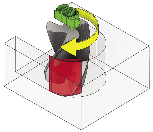
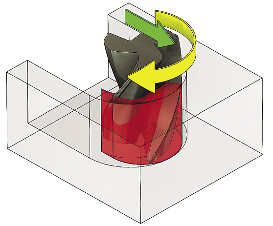
Toolpaths programmed with Mastercam's Dynamic Machining suite produce radial chip thinning (top), whereas a traditional toolpath (above) doesn't enable the productivity-enhancing benefits RCT provides.
New CAM toolpaths and cutting tool designs, such as those used in Mastercam's Dynamic Machining suite and Iscar's High-Efficiency Machining tools, push the advantages of RCT to its practical limit. None of this was possible until all the elements—including cutting tools, machine tools and CAM toolpaths—caught up to each other a few years ago. Therefore, now is the time to consider RCT for your operations.
Variable-pitch tools, in particular, have virtually eliminated harmonics during machining, and advances in tool coatings enable them to withstand temperatures up to 900° F (482° C). In addition, machine tools are faster and CAM toolpaths are producing movements conducive to full-depth cutting.
On the CAM side, local resellers can demonstrate how to gain efficiencies. As a result, machine shops are applying RCT to improve productivity 30 to 200 percent by reducing cycle times. They are also reducing costs via longer, more predictable tool life and less wear and tear on machine tools.
For example, one of our customers was consuming 70 minutes cutting pockets in mold bases. It was taking shallow step-downs and aggressive step-overs while running at high feed rates. We exchanged their tool with an Iscar tool made of higher-quality carbide designed for high feeds and reduced cycle time to 45 minutes. Next, we applied the Dynamic Machining toolpath calculations—stepping all the way down—and replaced the customer's traditional roughing operation. Time to cut the pockets fell to 12 minutes, an improvement of nearly 500 percent.
The combination of changing the tool and its motion also reduces tool cost per part, because tools last longer. Another money-saving aspect with these advanced machining techniques is coolant isn't usually required for heat removal when cutting most steels if the speeds and feeds are correct. Instead, chips are simply air-blasted away. Dry machining actually extends tool life, because the heated tool is not being shocked when coolant repeatedly hits it, which breaks down the coating and causes premature tool failure.
It's challenging for shops to try new approaches when the daily routine demands shipping high-quality work and current machining methods are achieving that. However, shops can do even better. All it requires is a conversation with your CAM reseller and tool vendor.
While the science of RCT can be confusing, the application is not. When the step-over is more than 45 percent, the productivity improvement will be modest. But the cycle-time reductions can be amazing when the step-over ranges from 10 to 35 percent. Remember, new dynamic toolpaths ensure the machine will not shove a tool into a part corner or have it do a full-width cut. Give it a try!


