

Surface Strategy: Turning Performance
Parts that meet drawing dimensions can still end up as scrap if they lack surface integrity.
Many manufacturers believe a part that meets drawing dimensions is a good part. But quality is more than that. It often includes meeting unstated functional needs, such as not breaking differently than past parts, not causing other parts to suddenly corrode and ensuring the material is homogeneous throughout. In addition, the part must meet surface quality requirements.
Courtesy of Proceedings of the International Association of Journals and Conferences
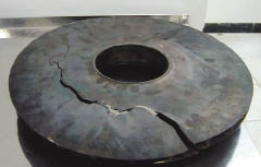
This fractured centrifugal compressor disk for the oil industry displays the impact of fatigue on a part.
Surface quality has two intrinsic aspects: surface appearance and surface integrity, which are based on the metallurgical and mechanical alterations from the base metal properties. Surface roughness is one attribute of appearance. Glass, ceramic and some metal parts also must meet requirements for surface gloss, luster, color, reflectivity and other attributes.
Some specialists lump roughness and surface integrity together because improper surface roughness can cause catastrophic product failure, but this article concentrates on the attributes of surface integrity. Those include no foreign material smeared on the surface or embedded in the material, and freedom from oxidation, hydration and stains.
In addition, acceptable surface integrity (includes subsurface issues) has no:
• burrs
• cracks
• molten metal or plastic
• heat-affected zones
• “white layer”
• crystallizing effects
• chemical changes
• chemical or physical absorption
Surface integrity also includes the presence of appropriate residual stresses (usually neutral or compressive), correct morphology or structure and correct grain orientation.
Unfortunately, with the exception of the requirement to remove all burrs, part drawings and specifications from smaller companies typically do not include surface integrity expectations. However, large corporations typically do include lengthy specifications that cover many surface integrity issues.
Courtesy of Air Force Machinability Data Center
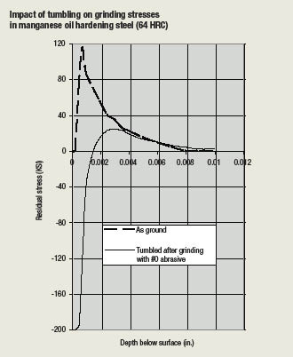
Figure 1: Subsurface stresses through the thickness of the part from grinding and tumbling.
The need for effective surface integrity control became a major driver with the advent of high-strength steels and similar materials for aerospace applications. Turbine engines, for example, tend to fly apart if certain surface integrity attributes are not maintained. Obviously, airline passengers take a dim view of turbine blades failing while flying. Oil field workers have the same lack of understanding when standing next to a high-pressure pump that suddenly explodes because a subsurface flaw caused premature failure.
Failure Starting Points
Burrs and minute surface cracks in heavily loaded structures are starting points for high-stress and corrosion failures. A small force at the outside of a crack is magnified greatly at the end of the crack. A crack keeps spreading because of the intense stress at its bottom. Burrs and cracks are high-energy zones that allow electrical and chemical actions to proceed faster than on the center of a flat, smooth surface.
Surfaces produced by electrical discharge machining are sources of several quality issues. EDMed surfaces are often rougher than the rest of the part. The EDM spark vaporizes the surface and some of that vaporized surface solidifies back on the workpiece as a recast layer that is not uniform with the parent metal. The EDM process, as well as laser machining, can also leave stretches of a brittle white layer under the surface of high-strength steels, which cause premature failure. Many specs indicate that a white layer is not allowed and others state that EDM or laser processes are not allowed because of this concern.
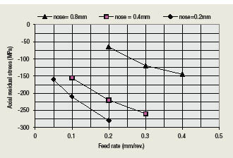
An unseen result of machining and heat treating is the creation of residual stresses. All mechanical chip-producing processes leave stresses in a part’s surface. The raw material has some stresses in it, but stresses from machining can cause a host of issues. First, tensile stresses reduce the overall strength of most parts. These stresses can be quite high, even higher than the material’s bulk strength (Figures 1 and 2).
Courtesy of Javidi
Review the print ads from this magazine to continue
This quick advertiser review unlocks the rest of the article and keeps the full-screen reader focused on the ads instead of the page chrome.
Advertisers included in this article experience
Print placements connected to this article
Mastercam
training program reports Advertorial
To receive additional information about the products and services described here, refer to the Product Information form on page 3. training program reports. cnc software inc. offers training kennametal inc.’s Knowledge Center Keeping workers abreast of the for its Mastercam CAM software through in Latrobe, Pa., provides expert instruction.
training program reports Advertorial To receive additional information about the products and services described here, refer to the Product Information form on page 3. training program reports. cnc software inc. offers training kennametal inc.’s Knowledge Center Keeping workers abreast of the for its Mastercam CAM software through in Latrobe, Pa., provides expert instruction latest technological developments its reseller channel and also offers in metalcutting application engineering. through training can help increase a online training at MastercamU.com. Courses are offered at the basic and manufacturer’s competitiveness. To All training classes include a certificate advanced levels, and include classroom, assist in locating metalworking training, of completion. Also, the Mastercam lab and machine demonstrations. presented in this special training section Certification program, a set of
Visit Mastercam View this placement in the issue recordPrint ads from this magazine
To receive additional information about the products and services described here, refer to the Product Information form on page 3. training program reports. cnc software inc. offers training kennametal inc.’s Knowledge Center Keeping workers abreast of the for its Mastercam CAM software through in Latrobe, Pa., provides expert instruction.
training program reports Advertorial To receive additional information about the products and services described here, refer to the Product Information form on page 3. training program reports. cnc software inc. offers training kennametal inc.’s Knowledge Center Keeping workers abreast of the for its Mastercam CAM software through in Latrobe, Pa., provides expert instruction latest technological developments its reseller channel and also offers in metalcutting application engineering. through training can help increase a online training at MastercamU.com. Courses are offered at the basic and manufacturer’s competitiveness. To All training classes include a certificate advanced levels, and include classroom, assist in locating metalworking training, of completion. Also, the Mastercam lab and machine demonstrations. presented in this special training section Certification program, a set of
Continue reading
June 2009
Figure 2: Average axial residual stress as a function of feed rate when turning 34CrNiMo6 steel.
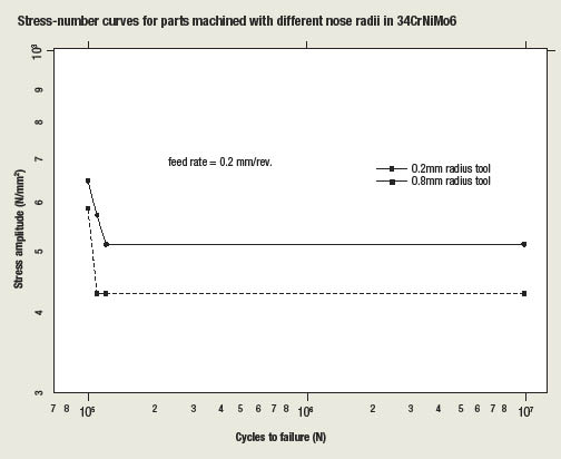
Residual tensile stresses also reduce part life due to fatigue. Repeated cycling of a material, such as back and forth flexing of a wing or slight bending of a shaft as it rotates each cycle, will not cause it to fail if the loads are kept below the material’s endurance limit. However, internal residual tensile stresses can lower the endurance limit below the historical or guidebook value. Figure 3 on page 53 illustrates some endurance limits on 34CrNiMo6 steel as a function of the feed rate. The part will last indefinitely if machined at 0.2 mm/rev. and the stress is kept below about 500 N/mm, but its endurance limit will be below 450 N/mm if the part is cut at a feed rate of 0.8 mm/rev.
Machining-induced residual stresses normally only exist a few thousandths of an inch below surfaces, but that’s where cracks begin and where high energies that are held between grain boundaries and within grains are available for undesirable actions, such as accelerated corrosion or rapid crack extension.
Strain Hardening Index
In addition to measuring stresses using X-ray diffraction or destructive etching, measuring the strain hardening index is another way to assess the depth of residual stresses. As a material is cold worked, strain hardening increases. A common material that strain hardens, or becomes harder when it is stretched or strained, is 303 Se stainless steel.
Machining and deburring can introduce beneficial compressive stresses that significantly improve a metal’s normal load carrying ability. Compressive stresses counteract the normally damaging tensile loads. The tumbling processes for deburring and surface finishing, for example, improve the compressive stresses through a gentle but firm peening of the surface as parts tumble against the deburring media. The aerospace industry commonly performs peening with metal shot or glass beads to add compressive stresses. Electrical and chemical finishing processes may remove some of the subsurface stresses, but they do not add any beneficial stresses. It is important when machining and finishing parts to closely control the chemistry, hardness and geometry of the finishing materials to assure consistency.
Stresses can relax over time, so a part that was flat at inspection develops an obvious bow by assembly time, which can be weeks later. The machining processes can cause it to bow later as a result of relaxation of internal stresses. Another possibility is that the raw material the manufacturer purchased has high stresses. For example, residual stresses in aluminum relax sharply several days after age hardening, but continue to relax up to 180 days later.
Some parts must be free of material left on the surface by the cutting tool, either from the tool itself or from a different workpiece material that the tool previously machined. Smeared metal and fractured microsurfaces are also common. Benchtop scanning microscopes are available for about $300,000 to inspect surfaces at 1,000× to 10,000× magnification and determine how much foreign material is on a surface. Because of the high cost, a shop should occasionally have an outside service check parts to determine if contamination is occurring.
Changing Elements
Machining or heat treating can also change surface elements. At high temperatures, some of the changed surface elements burn away and either weaken the part or promote crack formation. Machining can extract some of a carbide tool’s constituents, causing extreme tool wear. The same cutting conditions can similarly affect the workpiece.
Nickel-base superalloys have a high affinity for many tool materials, such as tungsten carbide. These elements form an adhering layer, which causes diffusion and attrition wear. Oxygen and nitrogen from the air at high temperatures during machining diffuse into surface layers of titanium alloys.
Machining hardened 4340 steel can cause patches of brittle, untempered martensite, which is seen as white layer after etching with a diluted nitric acid metallurgical etch solution to show metal grains. Under this layer is often a layer of overtempered martensite. Both layers reduce fatigue life.
Electrochemical or chemical processes can cause selective etching at grain boundaries (intergranular attack), which is another source of fatigue failure.
Even aluminum experiences chemical changes when machined with PCD tools. In a 2004 study by C.K. Toh and S. Kanno at the Singapore Institute of Manufacturing Technology, the oxygen, magnesium and silicon content fell at 20μm below the surface of 6061 aluminum, causing the aluminum content to increase from 96.8 to 98.2 percent.
Milling and turning can pull grains from the surface, leaving a cavity. For example, titanium and titanium aluminide experience this. Also, while most materials get harder when strained, some, like titanium, can get softer or harder.
Titanium grains can recrystallize from high machining temperatures and high strain rates and leave an amorphous layer on the surface. Amorphous in this instance indicates the material has no crystalline configuration. In a sense, it is similar to glass—a glob without substructure. That results in two different materials, which have two different sets of properties and two different resistances to loads and electrical, chemical and thermal effects. That is not a good combination for safety-critical parts.
Other workpiece materials can also experience surface quality problems. For example, Inconel 718 experiences surface tearing, cavities, cracking, recrystalization, plastic deformation, residual stress increases and microhardness increases below the machined surface.
Another problem is plastic deformation—the stretching of the subsurface material such that flow lines can be seen in cross-sectional views. It occurs in all metals, but is easiest to see in machined brass, which has large grains. This deformation, or stretching, of surface crystals occurs less in Inconel when the cutting speed is 60 m/min. or lower, but the unwelcome tensile residual stresses increase as cutting velocity increases. Machining with dull tools greatly increases many of the harmful aspects of surface integrity, particularly stresses, increased hardness and local deformation.
Surface Solutions
The unwelcome aspects of surface integrity are reduced when cutting with sharp tools, proper lubrication to minimize temperatures and proven feeds, speeds and tool geometries. As a general rule, increasing cutting temperatures results in higher tensile stresses, and mechanical rubbing adds compressive stresses. Because residual stresses are additive, using finishing processes that hammer surfaces, such as vibratory tumbling, shot peening or otherwise mechanically squeezing or burnishing the surface, reduces the tensile surfaces stresses left by machining and generally provides the desirable compressive stresses.
Courtesy of Javidi
Figure 3: Endurance limit as a function of cutting conditions in 34CrNiMo6 steel.
Proper heat treatment can also reduce harmful tensile stresses in some materials. Many of the military specifications define heat treating steps to control stresses, and most heat treaters have the knowledge to properly address stress concerns.
Surface integrity is not a common shop phrase, yet it underlines the quality of every part made. Because of the impact machining and finishing processes have on surface integrity, some military contracts specify that a process cannot be changed once it is approved. Changing processes changes the stresses, fatigue life, overall strength, corrosion resistance and a host of other potential factors, and some changes are not seen for months or years. Qualifying process changes can cost tens of thousands of dollars and take months of work. A part may meet all drawing requirements, but if a manufacturer changed the process, it is scrap.
The correct way to change a process is to always discuss your plans with the customer, who often isn’t aware of all the consequences a change can cause. For many situations, change is not a problem, but for others it breaks a written contract. CTE
About the Author: LaRoux K. Gillespie has a 40-year history with precision part production as an engineer and manager. He is the author of 11 books on deburring and 200 technical reports and articles on precision machining. He can be e-mailed at laroux1@earthlink.net.
Glossary terms in this article
Related



Subscribers can use MFGAxis notes, saves and discussion tools with their innoNET account.


