Tolerances Feel the Heat
Tolerances Feel the Heat
With close-tolerance machining, variances in the temperature of the part or gage can lead to out-of-tolerance work. This article describes the compensation systems that have been developed to measure temperatures and make the necessary adjustments to gage readings.
Machining tolerances have gotten steadily tighter over the past 150 years. During the Industrial Revolution, a tolerance of 0.10mm was considered stringent. Tolerances of 0.01mm began appearing on technical drawings in the 1950s. It's now common to find tolerances measured in 0.001mm units (microns).
Today, specified tolerances have reached the point at which many shop-floor measuring systems are subject to subtle but very significant errors as a result of simple day-to-day changes in ambient temperature. Designers often expect production workers to machine parts to the stated dimensions, but some people on the shop floor are unaware of the critical influence that temperature can have on part accuracy (Figure 1).

Figure 1: Temperature changes can introduce significant variation to the dimensions of a workpiece.
Part designers who are responsible for developing specifications and technical drawings need to be alerted to this matter, so that they can provide appropriate notification to production personnel. By addressing the issue, manufacturers can meaningfully improve their process capabilities.
Thermal Effects Can Affect Fit
Once technical drawings are finished, designers usually send them off to manufacturing and get on with the next job. It is assumed that the machine tools and inspection equipment used on the plant floor will ensure that the correct dimensions are obtained.
These machines and equipment are remarkably capable of delivering the desired results. However, their performance is affected if they're exposed to changing temperatures. And shop-floor temperatures aren't often precisely controlled.
The result is that machine tools, positioning systems, and gages can produce varying results, depending on the prevailing temperature. In many cases, the range of dimensional variation can exceed the total tolerance specified for a component's dimension.
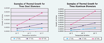
For example, a steel crankshaft-bearing journal might measure 3.0000" in diameter at 90° F, but at 70° F it will measure 2.9996". That 0.0004" can represent a large part of the total tolerance. If the journal was undersize by that amount and the mating bearing was oversize by the same amount, the overall performance of the assembly could be significantly affected. Components might wear more quickly than expected, or they might fit together too loosely or not at all.
According to ANSI Y14.5M-1982, "Unless otherwise specified, all dimensions are applicable at 20° C (68° F)." The very first standard published by ISO dealt with the same issue. ISO 1 (1975) ratified an international agreement that was reached in 1931. Consisting of just a single sentence, it states: "The standard reference temperature for industrial length measurements is fixed at 20° C."
On the shop floor, however, these standards are usually overlooked, ignored, or unknown. Consequently, an opportunity to maintain high quality and process capabilities is often missed. A part may appear to be within tolerance at the time of manufacture. But if measured under controlled conditions, the machinist might discover that it's actually out of tolerance.
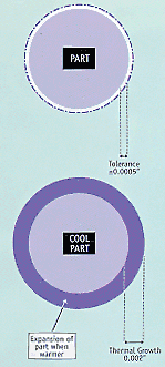
Tolerances have become so tight that, in many instances, the subtle effects of temperature have become significant. In fact, thermal expansion of part features during the production and post-production processes can now exceed the total tolerance (Figure 2). However, since the effects of temperature are so subtle, and the eye cannot discern changes in dimension that are measured in microns or tens of thousandths of an inch, it is easy to overlook this phenomenon.

Figure 2: With temperature variation, the thermal growth of parts can sometimes exceed the total tolerance specified for a feature dimension.
There is a Solution
The same technological trend that has driven tolerances down into the microscopic realm has provided the solution for dealing with thermal problems. Electronic temperature-compensation systems can correct for temperature-induced errors in real time.
These systems provide users with an economically priced method for minimizing thermal errors that can arise when manufacturing high-precision parts. They sense the temperatures of the key elements of a measurement system—the workpiece, gage, and setting master—calculate the amount of thermal error in that system, and output a correction signal. That correction, or compensation, can be applied automatically to a precision gage so that the measurements taken reflect true dimensions—those in which the elements are held constant at the international reference temperature of 20° C.
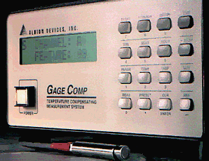
A temperature-compensation system consists of a microprocessor-based controller equipped with custom-designed temperature sensors and a selection of I/O ports. It can communicate with almost any electronic gaging system via an analog or digital interface. The device's sensors attach to the gage fixture to monitor the temperatures of the part being measured, the gage fixture, and the calibrating master or masters.
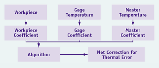
A temperature-compensation system can be programmed to take into account the effective coefficients of expansion of the part, gage, and master. During measuring operations, the system continuously senses temperature variations, then computes and sends a correcting signal to the gage. The gage then eliminates thermal errors and displays the correct measurement (Figure 3).

Figure 3: A temperature-compensation system can be programmed to take into account the effective coefficients of expansion of the part, gage, and master.
Environmental controls such as air conditioning, heating, and liquid coolant are expensive and inaccurate. These methods can cost thousands of dollars to purchase and operate annually, and, at best, they achieve repeatable thermal control of only ±2° to 3° F. Temperature-compensation systems provide accuracy on the order of ±0.5° F, and they cost much less. They have a one-time cost of $2000 to $20,000.
Temperature-compensation systems are designed to work with all electronic gages, including automated, column, and other benchtop systems.

Automatic temperature-compensation systems continuously sense temperature variations and send a correcting signal to the gage.
The Designer's Role
Hundreds of such systems are currently in service in a wide variety of plants. The systems were installed because these plants' production teams were warned that temperature fluctuations would generate measurement inaccuracies.
As a rule of thumb, when total tolerance represents one-thousandth of an inch or less of the nominal dimension of a part feature, temperature is probably going to significantly affect measurement accuracy.
And it is important to realize that all gages and positioning systems are affected by temperature. Although there may be offsetting effects, caused by the gage or master expanding or contracting along with the part, they invariably change at different rates due to their different effective coefficients of expansion.
It's not realistic to expect workers on the shop floor to remember to minimize thermal variations. Production personnel deal with many dimensional specifications, and the majority of the pieces they machine do not require finishes so accurate that temperature must be considered. As a result, operators may not be aware of the need to consider temperature for close-tolerance parts unless they are alerted to do so.
The designer of the part, however, will know that a close tolerance is being specified and should write an alert on the drawing. Designers of components can help everyone by clearly marking the drawings for temperature-sensitive parts with the words: "All Dimensions are Applicable at 20° C (68° F)."
By doing this—and therefore eliminating thermal variations in precision dimensional measurements—shops can significantly improve the quality of their products.
About the Author
Paul Sagar is president of Albion Devices Inc., Solana Beach, CA.


