Turning catching up in the use of chip thinning
Turning catching up in the use of chip thinning
Milling operations that benefit from chip thinning have become common, now it's turning's time.
High-speed machining, high-feed milling and high-efficiency milling are terms that have been incorporated into the modern machining lexicon. While nuances make their meanings slightly different—depending on whom you ask—all the techniques take advantage of radial and axial chip thinning.
Cutting tool manufacturers have been designing milling tools to exploit chip thinning while machine tool builders have been creating more dynamic milling machines that allow users to capitalize on the advanced tools.
As a result, milling operations that benefit from chip thinning have become common at many shops.
Turning operations that employ chip thinning have been slower to advance than milling operations. This lag is odd. After all, the chip morphology research that initially defined the characteristics of chip thinning was performed using orthogonal machining operations like turning and planing.
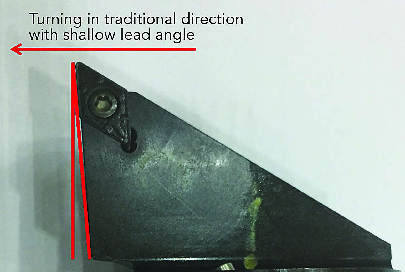
A common tool shape with a shallow lead angle produces a chip thickness roughly equal to the feed rate per revolution. Image courtesy of C. Tate
For a long time, toolmakers have sold turning and facing tools that hold square, triangle or other common-shaped inserts in an orientation that offers large lead angles. These angles allow increased turning feed rates, which exploit chip thinning. However, only recently have the cutting tool manufacturers and CAM software developers started to sell tools and toolpath solutions that can be called innovative.
One of the most effective, simple advances is used for heavy roughing of workpieces—such as large forgings—where high metal-removal rates are required and surface finish requirements and geometric tolerances are loose. Part manufacturers have applied rectangular inserts resembling large bricks of carbide with strong edge geometry. The inserts are held so the long edge is presented to the work in a tool body that creates a steep lead angle. Some manufacturers have demonstrated radial engagement of 1.3" with feed rates of 0.078 ipr. Compare these measures with the 0.187" DOC and 0.008 ipr feed rate of the standard CNMG inserts found at most shops.
In the Groove
Plunge turning, groove turning and multidirectional turning are terms that describe the practice of applying rectangular grooving tools to create grooves, along with a multitude of other part geometries. Before the proliferation of affordable CAM software and advanced machine controls, complex groove geometries were made with form tools. Turning tools would be form-ground to match the desired geometry so the programmer needed only to position the tool in the correct axial location and feed it into the part.
With the evolution of affordable software, creative programmers and machinists began using standard grooving tools to create complex geometries and forgo form tools. Cutting tool manufacturers responded with designs that aided this practice. They provided improvements that increased insert stability and research that tuned speed and feed data.
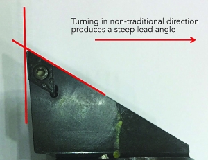
Newer tools and techniques capitalize on the step lead angle produced by using a common shape in a nontraditional way. The steep lead angle produces a thinner chip, thereby reducing forces and aiding chip control. Image courtesy of C. Tate
Although groove turning is effective, it has limitations—like causing chatter when applying small tools—that cannot be overcome by changing the design of the cutting tool alone. In the most recent advances, tool manufacturers have partnered with software developers to create tools and toolpaths that capitalize on axial and radial chip thinning, thereby reducing chatter. The techniques involve round inserts or large radii paired with light radial engagement and high axial feed rates. These methods not only reduce chatter but improve the mrr, impart finer finishes and often increase tool life.
Another recent advancement utilizes inserts that resemble standard ISO diamond and triangular shapes. The inserts are held in standard orientations and are capable of being used in traditional ways. However, the inserts are slightly different from the standard shapes as they have a compound angle and built-in edge that creates a very large lead angle when programmed correctly.
Traditional toolpaths move the tool axially toward the headstock of the lathe with a relatively shallow lead angle. Improved inserts combined with the proper toolpath produce relatively large lead angles that result in thinner chips and lower cutting forces. However, there's a trade-off because a large lead angle increases a tool's surface area on a part and therefore increases the tool pressure. Reduced cutting forces allow deeper radial engagement and higher feed rates culminating in higher volumetric removal rates.
Off the Beaten Path
Because the back of the insert is used, the programmer is required to change toolpath methodology by selecting toolpaths that move the tool away from the headstock. Developing these types of toolpaths is somewhat unconventional, so CAM systems are not always cooperative. In response to these developments, toolmakers are working with CAM developers to create canned turning routines that allow easy toolpath creation, which makes adopting the new methods much easier.
At Mitsubishi Hitachi Power Systems Americas Inc., we have successfully adopted some of these techniques, providing significant improvements to our machining processes. Safety is critical, and we address all situations that endanger our team. Our original machining processes produced bins full of stringy, unbroken chips. These placed everyone at risk of serious cuts but also created the risk of machinists being pulled into machines.
By adopting newer methods, we have improved chip control that is much safer and makes chip disposal and handling much easier. Newer grooving techniques have reduced the need for specials, reduced machining times and improved surface finishes.
Exploiting chip thinning by purchasing new cutting tools or buying more CAM software can be daunting for some shops, but it does not mean they are excluded from the benefits of chip thinning when turning. All major cutting tool manufacturers have chip thinning formulas in their catalogs, and the web, such as at YouTube, has a ton of good videos that demonstrate the techniques. Research and creativity can allow any shop to begin adopting more efficient practices.


