

Vibrations indicate bearing damage: General Industry Coverage
Many machine tool spindles are supported in the housing by rolling-element bearings. Cutting forces, spindle unbalance and spindle preload impose cyclic loads on the bearing's balls and races. Over time, the cyclic loading produces fatigue failure, damaging the surfaces of races and balls.
Many machine tool spindles are supported in the housing by rolling-element bearings. Cutting forces, spindle unbalance and spindle preload impose cyclic loads on the bearing’s balls and races. For example, a point on the inner surface of a race experiences a high-compression load as a ball rolls past, and that load is released after the ball passes.
Over time, the cyclic loading produces fatigue failure, damaging the surfaces of races and balls. This kind of damage causes vibration and noise, limits bearing life and eventually requires bearing replacement.
Courtesy of S. Smith
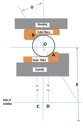
Figure 1. Cross section of angular contact ball bearing kinematics.
The occurrence and progression of damage can be detected by measuring vibrations on the spindle housing. Every time a ball passes a damaged spot on a race, it produces a “click,” and the frequency of the clicks can identify where the damage has occurred. As the damage increases, the clicks become stronger.
The frequency of the clicks can be determined from the bearing kinematics (Figure 1). At low spindle speeds, the inertia of the rolling element does not matter, and the ball makes contact with the inner and outer races at points A and B, respectively. The inner race rotates with the spindle shaft, and the outer race is fixed in the housing. If the rotational frequency of the shaft is ω, the velocity of point A is:

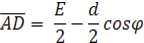
The velocity of point B is 0 because it is attached to the fixed housing. If the pitch diameter, measured across the spindle to the center of the balls, is E, the ball diameter is d, and the contact angle is φ, then:
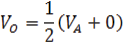
The velocity of the ball center is the average of the velocities of the two contact points:
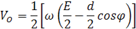
Combining those three equations gives the velocity of the ball center as:
The rotational frequency of the ball set and the separator is:
Review the print ads from this magazine to continue
This quick advertiser review unlocks the rest of the article and keeps the full-screen reader focused on the ads instead of the page chrome.
Advertisers included in this article experience
Print placements connected to this article
Iscar
Intelligently wave-shaped cutting edge guarantees reduced vibrations
Iscar promotes a wave-shaped cutting edge designed to reduce vibration and improve chip control in difficult materials.
Intelligently wave-shaped cutting edge guarantees reduced vibrations Iscar promotes a wave-shaped cutting edge designed to reduce vibration and improve chip control in difficult materials. Visit iscarmetals.com to learn more.
Visit Iscar View this placement in the issue recordPrint ads from this magazine
Iscar promotes a wave-shaped cutting edge designed to reduce vibration and improve chip control in difficult materials.
Intelligently wave-shaped cutting edge guarantees reduced vibrations Iscar promotes a wave-shaped cutting edge designed to reduce vibration and improve chip control in difficult materials. Visit iscarmetals.com to learn more.
Continue reading
February 2014

This is sometimes called the fundamental train frequency (FTF) and, in terms of the geometry parameters, is:
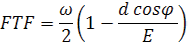
It is interesting to note that if the contact angle is 90°, the balls and separator rotate at half the speed of the shaft. If the contact angle is less than 90°, they rotate at an even slower speed.
In a similar way, it is possible to calculate the frequency with which the balls pass a point on the outer race, which is called the outer ball pass frequency, or BPFO, where N is the number of rolling elements:

The frequency with which balls pass a point on the inner race is called the inner ball pass frequency, or BPFI:
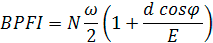
The ball spin frequency (BSF) is the frequency at which the balls rotate:
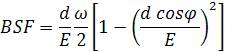
Because the geometric parameters are often hard to find, and the calculation can be confusing, some manufacturers provide FTF, BPFO, BPFI and BSF in tabular form. The table entries lump all the terms together except the spindle rotation frequency, and provide a “multiplier” for each damage-indicating frequency. If vibration is measured on the spindle with frequency BPFO, it indicates damage to the outer race. In addition, a BPFI frequency indicates damage to the inner race, and a BSF frequency indicates damage to the rolling element.
These parameters provide general guidance at low spindle speeds (hundreds of rpm). However, they do not work well at high speeds, because the centrifugal force of the balls causes the contact angle to change, and the balls exhibit both rolling and slipping. The clicks still appear and still indicate damage, but the measured frequencies do not match these equations. CTE
About the Author: Dr. Scott Smith is a professor and chair of the Department of Mechanical Engineering at the William States Lee College of Engineering, University of North Carolina at Charlotte, specializing in machine tool structural dynamics. Contact him via e-mail at kssmith@uncc.edu.
Related




Subscribers can use MFGAxis notes, saves and discussion tools with their innoNET account.


