



Warning track for stability limit
The Machine Technology column from the March 2011 issue of Cutting Tool Engineering eyes importance of establishing a warning track for a machine tool's stability limit.
Maximizing machine tool productivity requires knowledge of the stability limits imposed by metalcutting process physics. Selecting cutting conditions that exceed the stability limits causes chatter. Selecting cutting conditions that are too conservative avoids the danger of chatter, but underuses machine capacity.
It is important to stay in the stable zone, but how close to the boundary should you go? How accurately do you need to know where the boundary location is? The answers depend on the quality of the data and the repeatability of the setup. Computation of the stability diagram requires several pieces of information. Some are well known, such as the number of teeth on the cutter, and some are only approximate, such as the material properties.
There are two important workpiece material properties: the cutting force coefficient(s) and the process damping coefficient. The cutting force coefficient(s) relate the chip geometry to the cutting force. In a first approximation, meaning the approximation catches the major relationship as opposed to smaller effects the second and third appoximations catch, the tangential component of the cutting force is proportional to the frontal area of the uncut chip (chip width × chip thickness). The normal component of the cutting force is smaller, but proportional to the tangential component of the cutting force. Cutting force coefficient(s) are obtained via measurement with a table dynamometer mounted under the workpiece. The cutting force coefficients are adjusted to obtain agreement between the calculated cutting forces and the measured cutting forces.
Courtesy of Manufacturing Laboratories
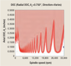
Figure 1. A stability diagram with “warning track.”
The measured forces are compared to the programmed chip geometry. The data is typically noisy, or inexact, and varies from one workpiece to another. To know the stability boundary precisely, some researchers define as many as eight cutting force coefficients to be identified. In addition to the workpiece material and chip width and thickness, some reseachers relate the cutting force to the cutting edge radius, feed, lubrication and other variables. For a single setup in a laboratory, this may be possible, but it is not practical to require so much data in a production environment. Beyond the first-order approximations, there is diminishing value from additional data.
The process damping coefficient indicates the inability of the cutting tool to regenerate short-wavelength waviness on the workpiece surface. The process damping coefficient describes the fact that when the spindle speed is very slow, a primary chatter-causing mechanism is eliminated. At slow spindle speeds, the waviness left on the surface by a vibrating tool becomes so short that the tool can’t follow it, and chatter stops. In essence, if the spindle speed is reduced enough, the cut becomes stable, and the process damping coefficient indicates the strength of that effect.
The dynamic characteristics of the machine are expressed in a frequency response function (FRF). This is obtained from a measurement near the tool tip when the tool is struck with a hammer and the resulting vibration is measured. The measurement cannot be made exactly at the tool tip, and, anyway, the cutting is distributed along a cutting edge. It is difficult to ensure that the hammer strike and vibration measurement are exactly aligned. As a result, the measured FRF is only an approximate representation of the machine tool dynamics in the cutting zone.
Some researchers advise measuring six FRFs: X vibration resulting from X force (a direct measurement), Y vibration resulting from X force (a “cross” measurement), and so on. For a 3-axis machine, there are three direct measurements (XX, YY and ZZ) and three cross measurements (XY, YZ and ZX). For most tools, the system is much stiffer along the tool axis than in the cutting plane, and two direct FRF measurements are sufficient. [Editor’s note: For measurement specifics, please refer to the July 2009 Machine Technology column.]
In addition to the factors previously listed, the repeatability of the setup must be considered. The FRF depends strongly on tool length, and that is set with some tolerance. The torque used to install the collet nut and the retention knob, the possibility that the operator may override the spindle speed, the possibility that the spindle speed may drop due to the cutting load, and the variability in stock geometry are all sources of uncertainty.
A rational response is to use knowledge of the stability diagram, but accept that the stability boundary is uncertain. It is valuable to choose cutting conditions in stable gaps between lobes, but it is dangerous to program close to the boundary, where small process changes might impact the outcome. One way to express this idea is to provide a “warning track” around the stability boundary (Figure 1 on page 26).
In the figure, the white area shows stable machining conditions, and the red hatched area shows chatter. The red line at the bottom of the hatched area is the best estimate of the stability boundary. The pink zone around that line shows uncertainty in the knowledge of the data required to compute the boundary and indicates that for cutting conditions in that zone, danger is near and careful control is required. CTE
 About the Author: Dr. Scott Smith is a professor and chair of the Department of Mechanical Engineering at the William States Lee College of Engineering, University of North Carolina at Charlotte, specializing in machine tool structural dynamics. Contact him via e-mail at kssmith@uncc.edu.
Glossary terms in this article
Related




Subscribers can use MFGAxis notes, saves and discussion tools with their innoNET account.


