Bystronic gets a ‘mega’ productivity boost
Bystronic gets a ‘mega’ productivity boost
Bystronic Laser AG, working jointly with EMCO GmbH from Hallein/Salzburg, undertook a complete redesign of the machine frame machining process so that it could be carried out by EMCO Mecof's Megamill high-gantry milling machine.
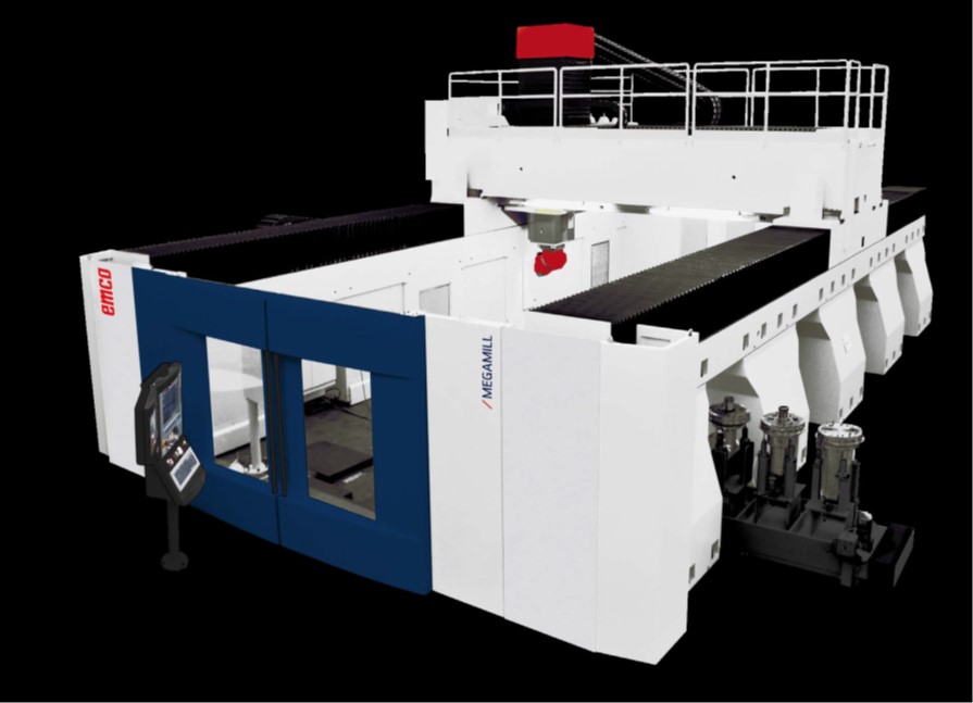
In machine tool manufacturing, one of the main preconditions for ensuring productivity and delivery readiness is a cleanly structured production process, with precisely timed production sequences and reliably functioning manufacturing systems. This can only be achieved if the customer and supplier take a common, goal-oriented approach to production chain projects.
That was the case for a similar project at Bystronic Laser AG in Niederönz, Switzerland. The company wanted to create a production line for machining the frames of laser cutting machines.
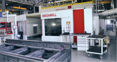
Bystronic Laser AG is a leader in the field of sheet metal processing, specializing in laser cutting systems. Working jointly with EMCO GmbH from Hallein/Salzburg, they undertook a complete redesign of the machine frame machining process, so that it could be carried out by EMCO Mecof's Megamill high-gantry milling machine.
A new partnership
"The machine frame quantities had risen to such an extent, that our existing production capacity could no longer keep up. As a result, we were looking for a new machine with sufficient output capacity, that could meet our high-quality requirements and would be flexible," said Raphael Kopp, head of production at Bystronic Laser AG.
Kopp had a clear idea of what he wanted from the new machine: a high rate of parts produced per month, perfect accuracy for plane milling the guide surfaces of the machine frames (evenness of 0.05mm on a guide track length of 3-4m), and flexibility to be able to produce different types of components. Most of all, the machine table also would have to be large enough, because the system assemblies for the laser cutting machines require considerable space.
After visiting several manufacturers and evaluating machining test results, it became clear within less than four months that the new machine should be a Megamill from Emco Mecof. Meanwhile, by working in close coordination, the key requirements and conditions for purchasing the machine were specified and verified, and the feasibility was demonstrated.
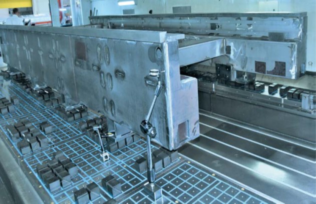
Kopp describes how they came to make the purchase decision. "The decisive factor was certainly the shuttle operation. In other words, we can now clamp two workpieces on the machine table, one is machined, and the second is inserted, aligned, and clamped in parallel. When the first part is finished, we move the milling head to the second half of the table and start the new job. The machine always keeps chipping away, so to speak. This brings us enormous savings in production time per frame."
Just-in-time production
At Bystronic, production throughput has to meet tough requirements. The production time for a laser cutting machine, from the automated welding of the machine frame, through manufacturing, painting, assembly, quality testing, and commissioning, to readiness for shipment, is 15 working days.
The production of a machine frame alone up to the painted component must be completed in five working
days.
With the Megamill, work is carried out in three shifts, with one unmanned shift. The machine frames, which are available in five different sizes and weigh around 5 t, are finished in 12 to 16 hours in a single clamping operation.
Complete machining is carried out in three steps:
• Roughing: Production time approx. 5 hours; component stress relief.
• Pre-finishing: Milling all features, holes, threads, etc.
• Finishing: High-precision machining of guide surfaces (flatness of 0.05mm /4m) and reference dimensions.
Production must be process-reliable, because, with this extensive production spectrum, malfunctions and errors, machine downtimes of longer than a single day can result in considerable costs, and machine frames are not kept in stock once they are finished.
Potential for its customers
The Megamill is a high-gantry milling center with an overhead gantry, ideal for machining large workpieces for applications such as machine tool and mold making, general mechanical engineering and aerospace.
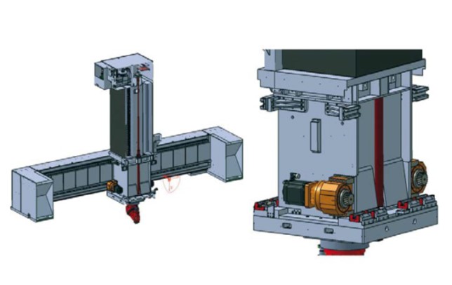
The system modules of the machine can be configured to meet the customer's specific requirements. At Bystronic, it is in a configuration with a table length (X-axis) of 15,000 mm and a transverse axis (Gantry- Y-axis) of 5,000 mm. The Z-slide (RAM) has a travel of 1,750 mm. Bystronic chose a universal milling head from the very wide range of milling heads offered by Emco Mecof. Not least of which because the 2-axis head with a torque of up to 1,000 Nm and 8,000 rpm perfectly meets the production requirements for roughing and finishing and, thanks to its compact design, can easily reach the frame contours which are complex to access.
Dynamic positioning generates time savings in a 16-hour machining cycle.
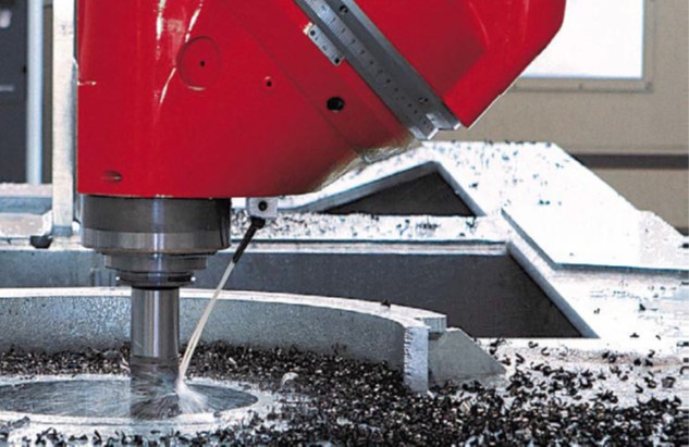
"The speed of the rapid traverse of the axes and the dynamic performance of the milling head produce measurable savings in machining time, especially when we have to drill more than 50 holes in the component," said Kopp.
In addition, the rack and pinion drives in the X and Y axes, each equipped with two motors running in a master-slave configuration, add dynamics to the process. And, pendulum machining on the table is a major advantage. The work areas are designed to prevent safety risks, ensuring that falling chips and access by the machinist are kept securely separated. Setup is performed on one side of the machine while the milling head is working on the other side. In this application, the Megamill is equipped with two control panels, so that the machinist can intervene on either side of the table.
The box-in-box design of the moveable crossbeam is another of the machine's strengths. The box-in-box means that the vertical axis of the RAM is clamped to the upper and lower sides of the crossbeam with its quadruple linear guides. This rigid, FEM-calculated assembly guarantees compliance with the stringent workpiece quality specifications that are required for the finishing of the guideways on the machine frames.
The machine is completely enclosed and equipped with a suction system.
Commissioning encounters some hurdles
The planning of the project, which started in 2017, the configuration of the machine and its construction at the Emco Mecof plant in Belforte Monferrato all went smoothly.
Then in autumn 2018, came the moment to deliver it to the customer's site in Niederönz. Loaded on 13 trucks, the machine was on its way to being installed and commissioned. It was then that problems started because although Bystronic planned to have a new production hall, it was not yet completed and the machine had to be placed somewhere.
Due to the access difficulties, part of the roof of the hall was removed and the crossbeam weighing approximately 30 t was placed on the longitudinal beams through the roof opening. It was a job that required extreme precision.
Part of the machine and the tool magazine with the tool changer had to be left out in the open. To enable commissioning to become possible, a separate enclosure was built around the parts of the machine which were standing outside. Compounding the problems, just at the same time, production quantities needed to be increased, so the ramp-up took place practically under emergency conditions. These kinds of imponderable situations happen all at once.
Efficient 2-axis universal milling head
The machining heads are built in-house at Emco Mecof, an important factor for determining machining accuracy. Emco Mecof also places great importance on the accuracy of the traverse movement of the axes, to achieve, for example, near-zero backlash.
Achieving the maximum possible accuracy is one of the main objectives of the Emco Mecof machines. As well as the wide range of standard heads, Emco Mecof frequently develops innovative dedicated customer-specific solutions, in particular for their series of large-gantry machines.
In the Megamill series, the machining heads with integrated rotary axis and swivel axis have infinitely variable, motor-driven adjustment and control and are available with a geared or high-speed motor spindle. Thanks to the intelligent layout of the head design, it can be positioned to perform an undercut of 15° while in a horizontal position (0°) parallel to the table surface. This is useful because it eliminates the need for compensation paths in the axes and simplifies program creation and post-process generation.
The machining heads are cooled by the central cooling system, which also feeds the spindle and torque motors. For Bystronic, these head kinematics meant embarking on new territory. The kinematics of the previous machines allowed the work programs to be programmed on the control panel. On the Megamill with its 2-axis head, this was no longer efficient.
To create optimal sequence programs, a CAM tool had to be procured. Its implementation was then actively supported by Emco Mecof. Coordinate transformation, and milling head retraction sequences, on all these topics, Emco Mecof was able to pass on its years of expertise to the customer.
Unmanned machining
Adjustment and subsequent clamping of the machine frame on the machine table were previously done by hand. The part is laid on support surfaces which are imprinted on the table.
This procedure was time-consuming, which soon prompted Bystronic to think of an idea for a different method of clamping. Based on their gained experience with magnetic clamping technology, which is also used in the factory, this technique was then also used to clamp the machine frames on the Megamill. The ends of the part are pre-leveled so that it is placed on the table at an angle.
Then the magnetic clamp, adjusted by wedges in the clamping segments, moves to all the support points and clamps the part. This eliminates the time-consuming manual alignment and clamping of each support point.
This method is particularly efficient and timesaving when, to eliminate internal stresses in the part, the clamp is aired for a period after pre-roughing the contour. This can now be done by the machine's control system. Manual intervention is no longer necessary. Instead, a sequence program written by Emco Mecof is stored in the control system. This can then be called directly via the M command to initiate the unclamping process.
The operator now no longer needs to go through all the clamping points, releasing the clamps and then tightening them again to 200 Nm, and do this twice for each part. This means that, in the unmanned shift, the sequence is guaranteed to be highly accurate.
A practical solution has also been found for any malfunction due to drill breakage during this period. The machine ends the current machining operation, moves in shuttle mode to the next prepared part and starts a new cycle. Reworking on the interrupted sequence is then done manually because it is critically important for Bystronic that every workpiece comes out correctly machined.
"The very good customer-supplier relationship that we had built up during the project was a real advantage when implementing our new idea of changing to magnetic clamping technology. We cooperated with professionalism and in a spirit of partnership." Kopp is extremely satisfied with the current production process. Since February, Bystronic has been producing parts using magnetic clamping. they have experienced no problems and made substantial Savings In Setup Time.
The future is here
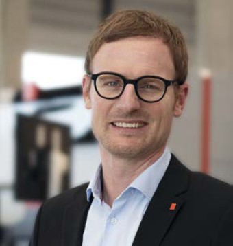
The managing director, Fabian Furrer, is an advocate for Bystronic's strategies for the future, and in his words, "our ambition is to be climate-neutral by 2025 and completely phase-out fossil fuels. We are achieving this by switching off oil and gas heating systems and working with heat pumps, whose electricity requirements are supplied by PV systems. We already get electricity from hydropower."
When reflecting on ways to save energy consumption. he applies the same sense of ecological responsibility that each individual has for an environment worth living in.
"We have to optimize our products too, in terms of their energy efficiency. The laser cutting systems for example, so our customers can also make savings."
In 2018, Bystronic initiated a new company activity, the Solution Center, where solutions are developed for digitally networking the whole production system at a customer's plant. The goal for all innovations developed here is the Smart Factory.
"Customers are increasingly asking for completely networked production, and we have to be able to provide that," said Furrer.
The right machine
Business and production management are in agreement after four years of experience in manufacturing
machine frames on the Megamill:
"Now after four years, we can say without a doubt, the Megamill is exactly the right machine for our production," said Furrer.
He particularly emphasizes that the specified requirements for the machine have been fully met and that they will be able to use the machine to implement new ideas in the future. On this subject, he already has some concrete ideas.
"We have optimized throughput times, we now achieve high productivity, and currently run 30-40% unmanned. But we intend to continue in this direction and expand unmanned production. With this machine, it should be no problem."


