Choosing the right tool for machining titanium
Choosing the right tool for machining titanium
Machining titanium cost-effectively requires special attention to the distinctive features of this material – particularly for choosing the right tools.
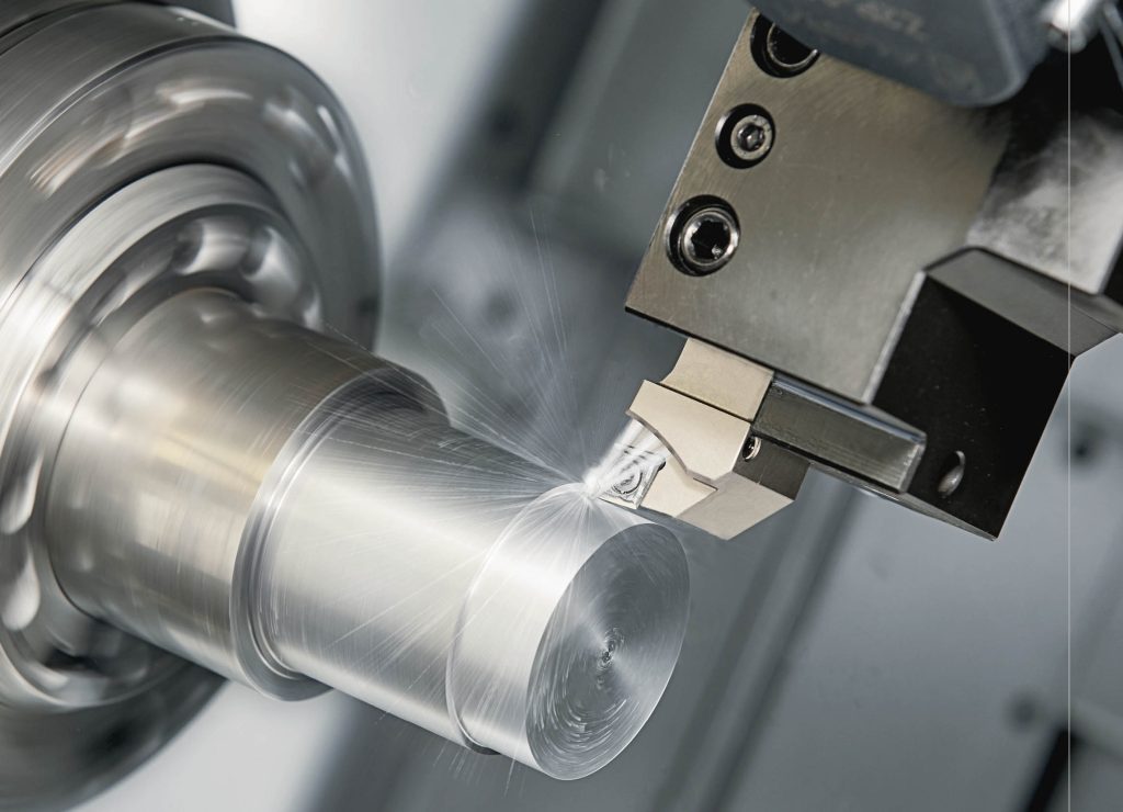
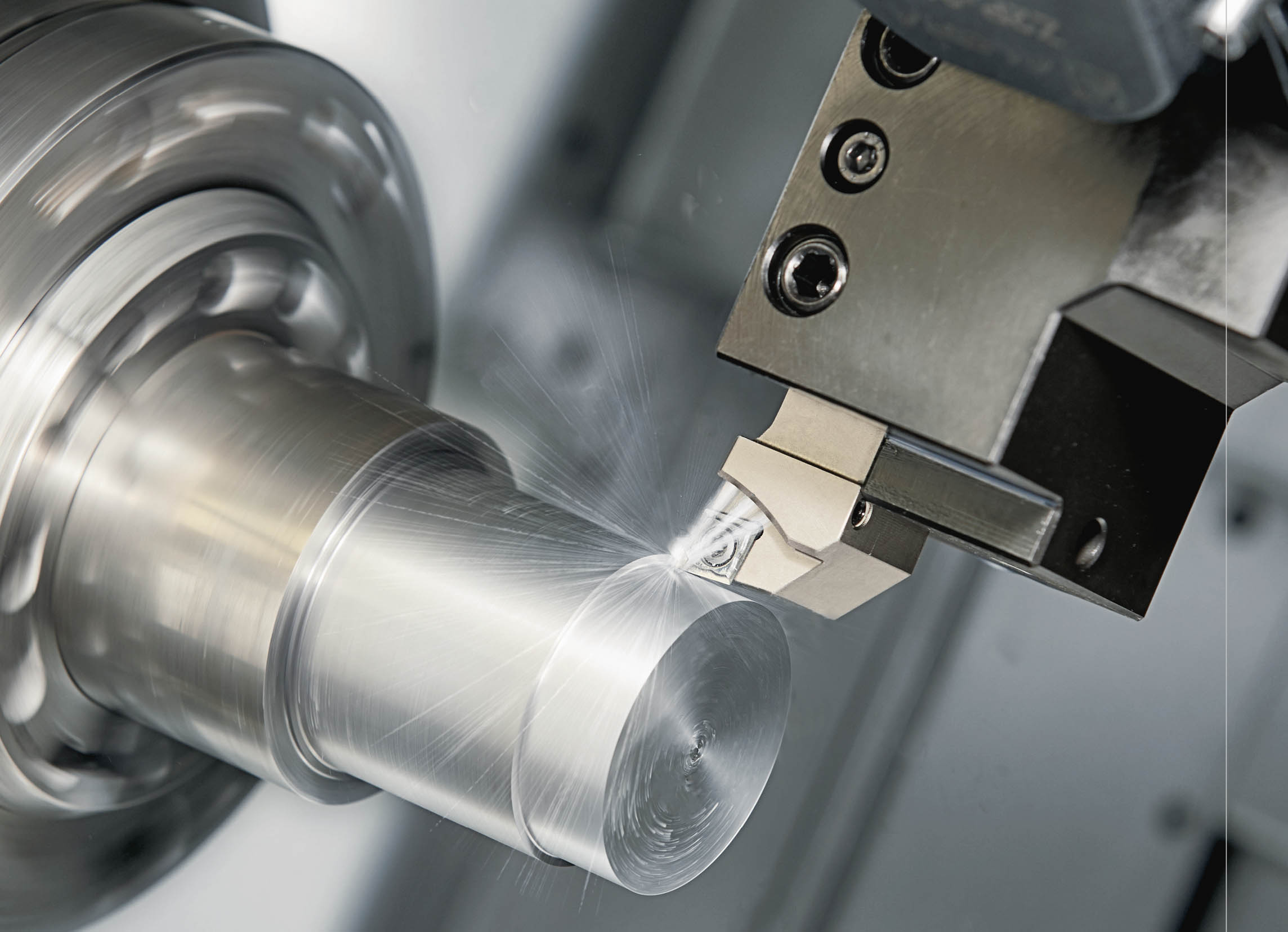 Machining the superalloy titanium requires special care and attention. Chips that won't break, heat that won't dissipate, and built-up edges are some of the common challenges of machining titanium.
However, titanium's remarkable properties make it a favorite in aviation, motorsport, and medical technology, so it is worth learning how to machine it properly.
Titanium's properties make it a superalloy. The material is extremely tension-proof, very light, and resistant to corrosion. In addition, titanium is antimagnetic, biocompatible, and resistant to even the most aggressive media. This expensive material is becoming popular in more fields and applications. It's no secret to the engineers at Bugatti, who use many titanium parts in their work.
Titanium is expensive – avoid waste
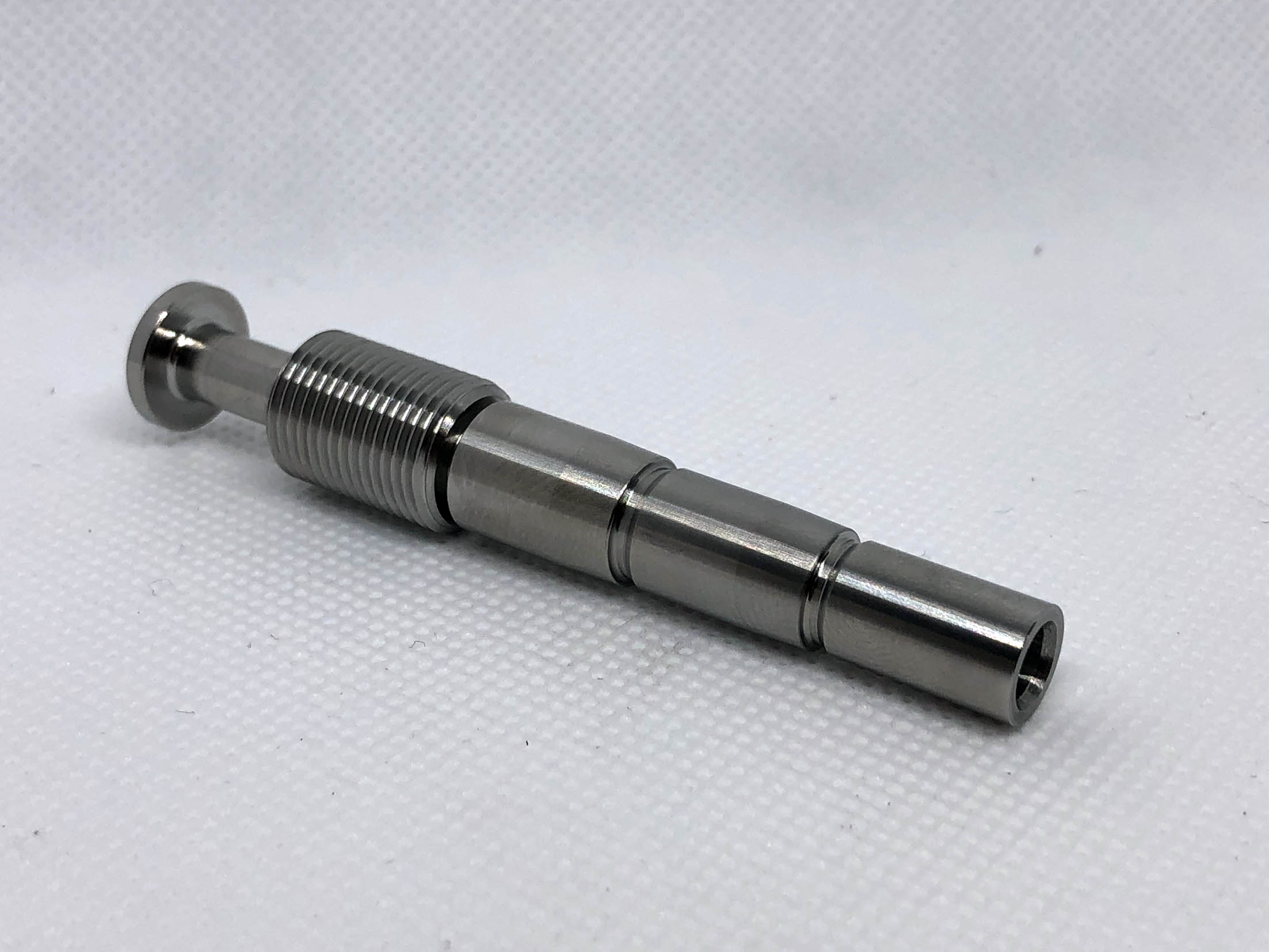 Machining titanium is an investment, as it costs about three to five times more than tool steel. So logically, users to avoid waste. The careful selection of a suitable cutting tool is only the first step. Manufacturing precision turned parts made of titanium requires tools that are suited to machining this particular material, allowing for the most stubborn titanium alloys to be machined as needed.
But this diva of the materials world can do a number on your cutting tools due to:
- · High heat resistance (see diagram)
- · Chips not breaking
- · Titanium's distinct tendency to stick to cutting tools
- · A low elastic modulus
(Ti6Al4V = 110 kN/mm2, steel Ck45 = 210 kN/mm2)
Since only a privileged few manufacture titanium screws for the 1500-HP Bugatti Chiron super sports car, let's instead take a look at the manufacture of a threaded and grooved shaft made of the standard titanium alloy Ti6Al4V Grade 5/23, as is frequently used in medical technology. With a Stress at which a material exhibits a specified deviation from proportionality of stress and strain. An offset of 0.2 percent is used for many metals. Compare with yield strength." title="In tensile testing, the ratio of maximum load to original cross-sectional area. Also called ultimate strength. Compare with yield strength." aria-label="Glossary: tensile strength">tensile strength…" title="Stress at which a material exhibits a specified deviation from proportionality of stress and strain. An offset of 0.2 percent is used for many metals. Compare with tensile strength…" aria-label="Glossary: yield strength">yield strength." title="In tensile testing, the ratio of maximum load to original cross-sectional area. Also called ultimate strength. Compare with yield strength." aria-label="Glossary: tensile strength">tensile strength of Rm = 990 N/mm2, yield strength of Re = 880 N/mm2, a hardness of between 330 and 380 on the Vickers hardness scale, and elongation at fracture A5d of approximately 18%, this titanium alloy is typically used for medical implants as well as aviation applications (3.7164) and industrial applications (3.7165). With six percent aluminum and four percent vanadium, and extra-low interstitial elements (ELIs), this alloy is highly biocompatible, inducing virtually no known allergic reactions.
Evacuate heat from the cutting zone
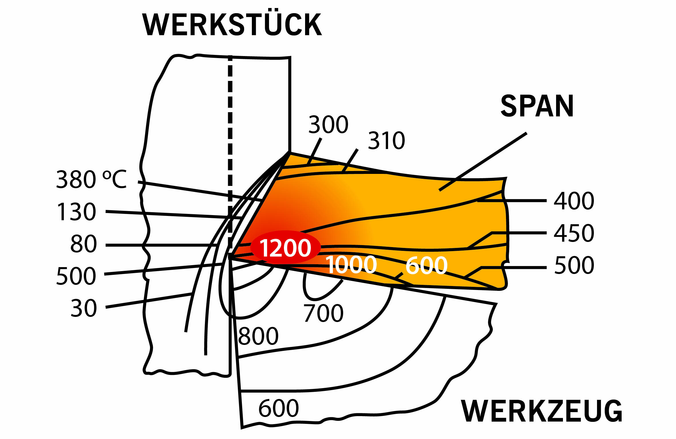 To evacuate heat from the cutting zone requires a high-quality surface finish, reliable process safety, and controlled chip removal, all while keeping process times short despite potentially high rates of chip removal.
Users might assume that most of the heat generated in the chuck, mounted on a face plate or secured between centers and rotated while a cutting tool, normally a single-point tool, is fed into it along its periphery…" title="Workpiece is held in a chuck, mounted on a face plate or secured between centers and rotated while a cutting tool, normally a single-point tool, is fed into it along its periphery…" aria-label="Glossary: turning">turning process is evacuated via the chips, but this isn't so. Since titanium is a poor thermal conductor, the heat cannot be alleviated from the cutting zone via the chips. And, at temperatures of 1200°C and higher in the cutting zone, the cutting tool can quickly sustain heat-related damage.
The easiest things to do to prevent too much heat from building up are to feed coolant directly to the cutting zone, reduce the cutting force by using a sharp cutting edge, and adjust the cutting speed to suit the process at hand.
Tools to increase service life
Real improvements are made by selecting the correct cutting tool. Since the heat must be evacuated via the cutting edge and the coolant, not via the chips, as is the case with steel, a small portion of the cutting edge must withstand extremely high thermal and mechanical stress.
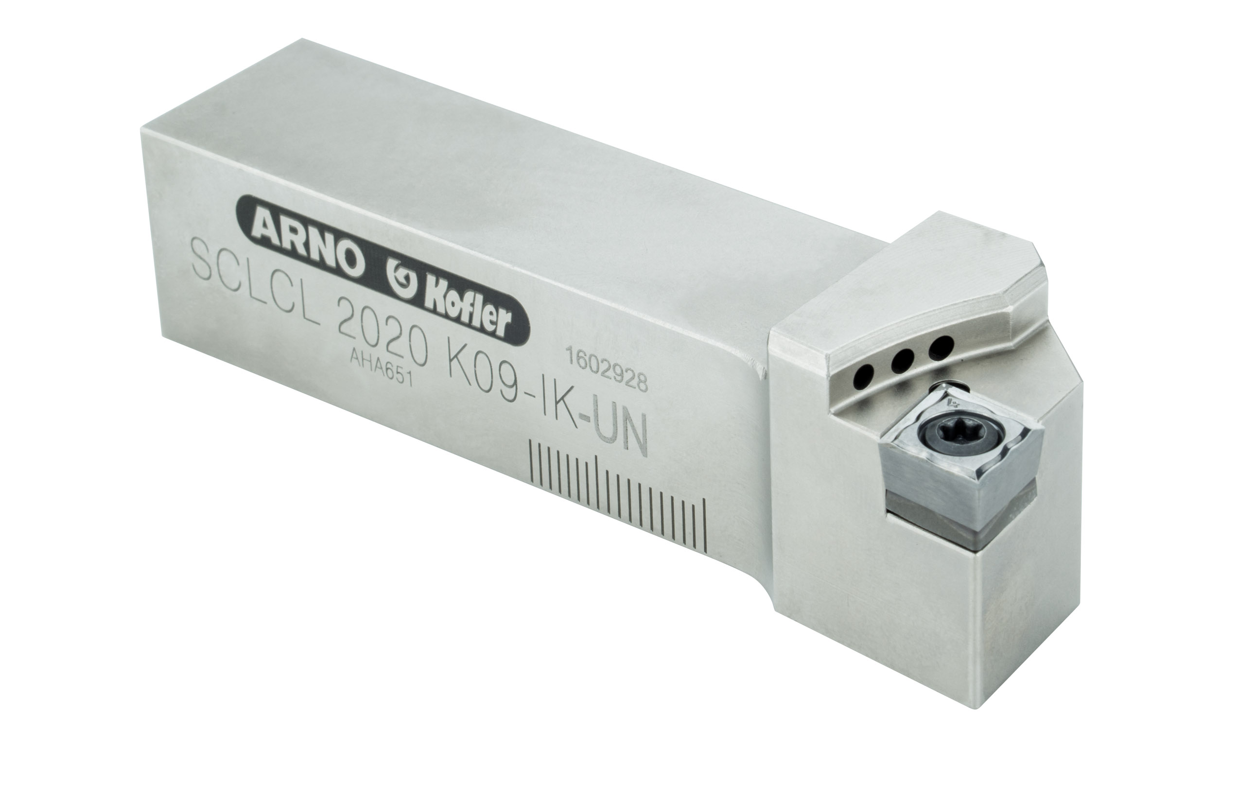 The cutting pressure is reduced by using ground, high-positive indexable inserts with polished flutes, if necessary, with the appropriate coating, minimizing friction in the chip removal process. These three parameters help prevent heat from being produced in machining. If only a little bit of the heat is reduced further through optimal coolant flow, the cutting edge will have a longer service life. Or the cutting speed (Vc) can be increased again to improve productivity.
So far, so good. But since the chips don't like to break, other difficulties may be faced. An endless chip could wind itself around the workpiece, tool, or the machine chuck and pose a hazard to the machine or your safety. It could help to change the direction of rotation and turn the cutting edge around if the machine's design allows it.
If the cutting edge is pointing downward, chips will fall freely to the ground and no longer pose a danger. However, when working with demanding roughing applications and less-than-stable machinery, users will have to check whether the cutting action allows the chips to be directed towards the machine bed. After the chips have left the work zone, they can no longer disrupt the process.
Choose the appropriate tool manufacturer
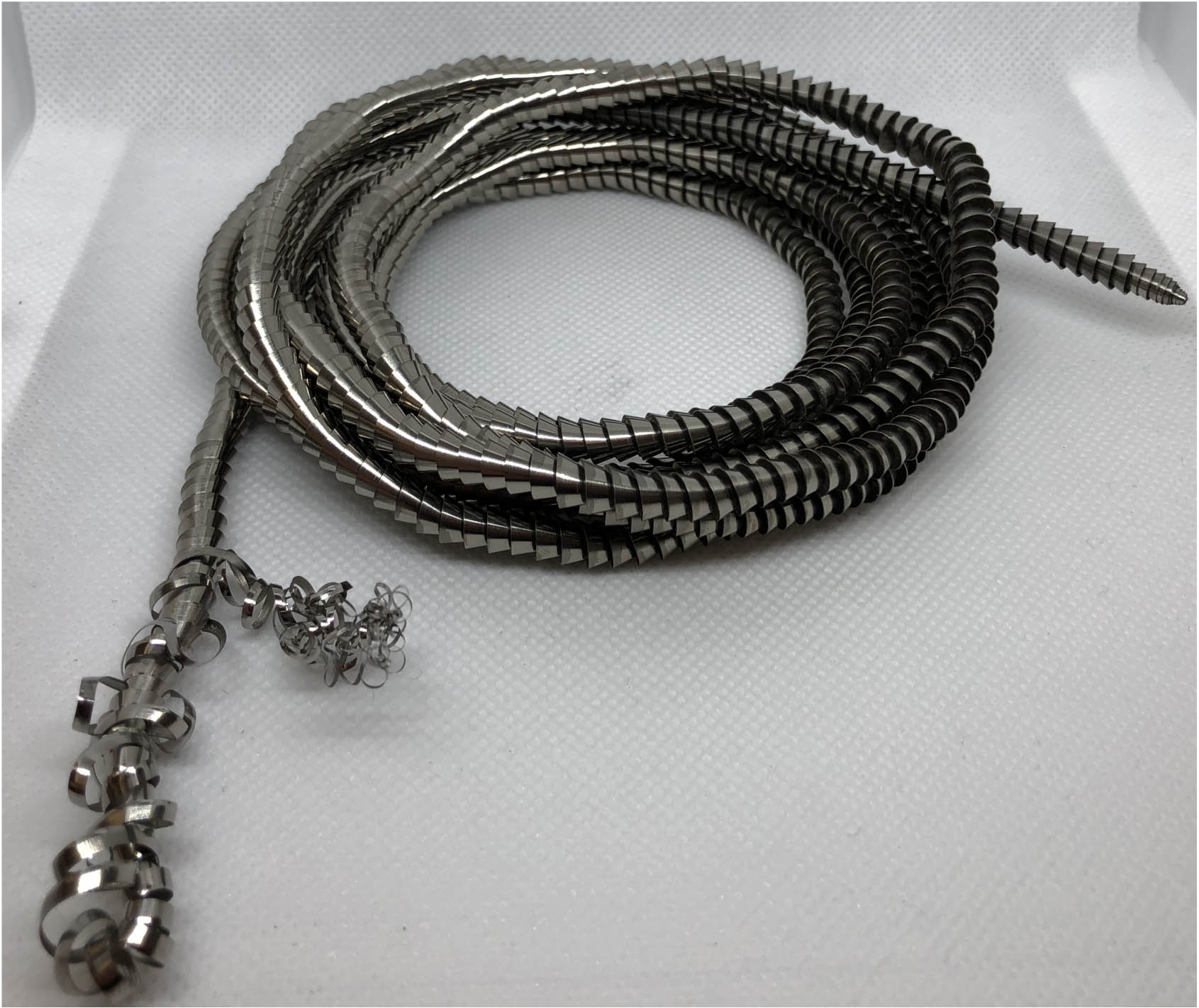 To ensure the user chooses the right tool for titanium machining, turn to a manufacturer. Some go above and beyond, offering advice based on specific application experience in addition to supplying the cutting tool itself.
For instance, ARNO Werkzeuge is a tool manufacturer that has been around since 1941. In addition to manufacturing one of the largest selections of high-positive indexable inserts, it employs many experienced application consultants who would be happy to share their knowledge to ensure that customers' manufacturing processes run smoothly.
Its high-positive indexable inserts are sharp enough to keep cutting force to a minimum, and their optional rounded edges ensure excellent stability. Expedient high-tech coatings make them well-equipped against the poor thermal conductivity of this tricky material.
Negative indexable inserts with EX, NFT, NMT, and NMT1 geometries provide an affordable, reliable solution for more basic machining and roughing. Arno's positive indexable inserts with geometries PSF and PMT1 are ideal for machining superalloys. All of these inserts are highly resistant to notch wear and heat when machining tough material. Unique geometries ensure exceptional chip control and process safety. Dedicated titanium machining experts and ARNO customers are well prepared. After all, you never know when you're going to get that call from a Bugatti engineer.


