Maximizing spindle idle-time reduction
Maximizing spindle idle-time reduction
Eliminating unnecessary interruptions to production directly affects machining cycle times, costs to complete each part from start-to-finish and, by extension, the ability to bid competitively. Getting more hours a day out of your spindle is key to optimizing this equation.
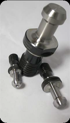
Article from JM Performance Products Inc.
Eliminating unnecessary interruptions to production directly affects machining cycle times, costs to complete each part from start-to-finish and, by extension, the ability to bid competitively. Getting more hours a day out of your spindle is key to optimizing this equation.
A study by machine tool builder Makino, Mason, Ohio, provided statistics about the impact of machining capacity idle time. The most notable revelation in this study was that the average vertical machining center, even when it's in cycle, isn't cutting 30% of the time. Even more revealing is that the real cutting, that other 70%, is likely much slower than what's realistically achievable with today's technology.
According to Makino, if you factor in all the other time your machine isn't running, such as setup, workpiece load/unload, cutting tool maintenance and clearing chips, and the typical VMC is working 34% of the time. Multiply all those wasted hours by your shop rate, and that's what non-cutting time is costing you day after day, year after year.
An innovator of CNC mill spindle optimization products, Fairport Harbor, Ohio-based JM Performance Products Inc. takes a look at the goal of increasing cutting time–from the angle of toolholder expansion at the spindle.
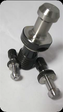
The Toolholder Factor
Industry wide, a major culprit of the majority of V-flange tooling issues machinists battle with on a daily basis is toolholder expansion. A myriad of production issues arise from this factor including: vibration and chatter, increased runout, poor finishes, tolerances, repeatability, increased machine and spindle wear and tear, and increased setup times. The collective impact of these issues is directly related to the number of parts that can be produced efficiently in a given cycle.
The average amount of toolholder expansion industry wide is 0.00035", or 1/7th the width of a human hair. This nominal amount of expansion is enough to inhibit complete toolholder taper-to-spindle contact and reduce tool life significantly. In essence, the lack of contact is equivalent to the motion of a bell clapper in that the holder moves randomly within the spindle. This occurs because once the small end expands, the point of full engagement (or contact) between the toolholder and the spindle reverses from the gage line to the small end. The bottom line is that the toolholder and tool are loose in the spindle.
Using V-flange tooling when CNC milling is inherently flawed by design. Notably, toolholder expansion occurs at the small end of the holder when a standard retention knob is installed. Extensive testing has proven that a standard retention knob has the potential to expand the small end of the toolholder when it is installed with as little as 20 ft./lbs. of torque–with a CAT 40 toolholder beginning to expand at 15 ft./lbs. Of note, the extent of this expansion is variable, depending on the holder, the retention knob and the installation practice.
Toolholder expansion causes tooling variabilities and critical machining issues that machinists must make adjustments, which include slowing down speed and feed rates, or taking shallower cuts. Every adjustment adds cost to parts in terms of tooling, increased cycle time, and lost production. It stands to reason, therefore, that reducing the variables that impact spindle performance can extend tool life significantly and increase productivity by 10% to 40%.
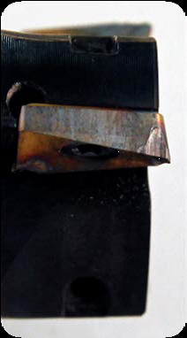
Note the wear pattern on this insert after 93.435 cu. in. of material removal using a standard retention knob.
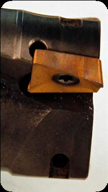
An insert after 186.867 cu. in. of material removal using a High Torque retention knob shows significantly less wear.
Standard Knob Expansion Vs. High Torque Solution
A toolholder should make 85% to 90% taper contact with the spindle for maximum rigidity, with solid contact at the gauge line. Retention knob induced expansion will prevent even dual contact toolholders from properly seating with the spindle. If it doesn't fit the spindle precisely, a critical "loose-tool" factor occurs that can create the perfect storm for chatter, poor tool and spindle life and decreased productivity.
Toolholder expansion caused by standard retention knob installation, can reduce the toolholder to spindle contact by 70% or more. Carbide tool life is diminished by 50% for every 0.0005" distance short of full engagement.
Identifying toolholder expansion can be achieved by simply looking at the wear patterns on the toolholder itself. Wear marks at the small end or at the gauge line, with no wear in between, are a clear indication of toolholder
expansion.
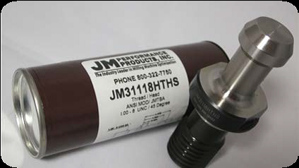
JM Performance Products has been spearheading the charge to overcome this "spindle-to-toolholder" relationship production obstacle–by directly addressing the inherent flaw design in V-flange tooling with the company's patented "High Torque" or lower-deformation retention knobs. The essential element of the design is a knob that is longer and reaches deeper into the holder's threaded bore. As a result, all thread engagement occurs in a region of the toolholder where there is correspondingly more material to resist deformation.
Additionally, High Torque knobs feature a precision pilot to increase rigidity, and a relief below the flange that forces threads into a deeper cross section of the toolholder. These design elements eliminate the toolholder expansion responsible for costly and ongoing CNC milling and boring issues.
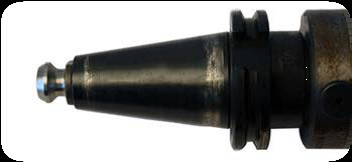
Fretting marks on the small end of the toolholder and on the gauge line.
Calculating Spindle-to-Toolholder Results
The Makino machining capacity idle-time study provided a cost calculator profile that illustrated the potential savings of over $17,000 a year that can be realized by reducing non-cutting time (idle time) by 29.4%. Core elements of this savings is realized with new technology and new equipment, and is extrapolated to $350,000 over the course of a five-year lease. The study also highlighted how an additional $5,200 in savings can be recovered by being able to access the tool magazine while the machine is in cycle; and another $10,400 in combined savings resulting from improved chip removal and coolant management, coupled with improved ergonomics.
The results of this calculation spotlight considerably large savings to be realized by upgrading to newer technology and equipment. JM Performance Products takes this example to another level by calculating an additional layer of savings that can be achieved based specifically upon improved spindle-to-toolholder contact. The results of this analysis prove as follows based on this simple, real-world equation:
Take 2,000 hours (approximately 1 shift) x $100 shop rate = $200,000 gross production. Then, add a few tangible details to this model: number of tools: 30; monthly tooling cost: $1,000; hourly setup rate: $25.00; number of hours per week for setup: 5.
If you can conservatively affect a 10% savings across the board, this is what the realistic breakdown results achieved would look like:
▪ 10% savings in tooling = $1,200
▪ 10% increase in production = $20,000.
▪ 10% setup savings = $650
▪ Total Savings: $21,850
Even with moderate results of 10%, $21,850 represents a significant savings. Of more importance is the fact that it would cost only about $900 one time to realize this savings potential. Beyond the conservative 10% barometer set forth in this example, realistic production increases should be 15%-40%. This would represent savings of $30,000 to $80,000 and that doesn't even factor in a 10% to 200% increase in tool life. Other ancillary savings such as setup time and maintenance costs should also be absorbed into this equation as well.
Gaining a Competitive Edge
Adopting advanced technologies to decrease machining time is paramount to gaining a competitive edge for
component manufacturing in vital growth industries such as aerospace, medical and automotive. Over the past 40 years, CNC machines and the tools used in them have evolved and advanced significantly, as mills are running at faster spindle speeds, changing tools in microseconds and have more horsepower.
A machine's ability to perform well in all of these aspects—power, torque and speed—is especially critical to shops that cut a variety of materials. Notably, high-speed machining in excess of 20,000 rpm is often utilized when machining components out of exotic alloys and harder metals like titanium and stainless steel.
According to JMPP President John Stoneback: "Tools have become more specific to the materials and processes, with suggested faster speed and feed rate capabilities. The only thing that has not changed is the retention knob. Improper installation, poor spindle maintenance, lack of skilled machinists and using the wrong tools are part of this equation. Most importantly, the trend toward moving away from standard retention knobs, with their inherent V-flange deficiencies is vital. Progressively adopting High Torque retention knobs to address this deficit and respond to the growing stresses of today's manufacturing is paramount to prolonged success."


